End Mill Selection for Server Liquid Cooling Plates, Flow Channels, and Manifolds
Introduction
Server liquid cooling components require more than efficient material removal. Flow-channel accuracy, burr control, thin-wall stability, sealing-surface quality, and batch consistency all depend on the end mill, toolpath, workpiece material, and machining setup. This guide explains how to choose milling tools for cold plates, manifolds, distribution blocks, and related precision cooling parts.
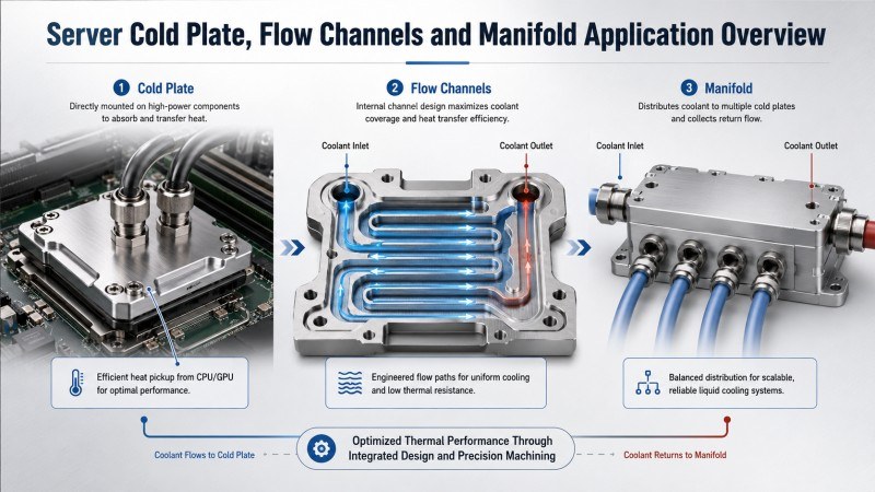
Liquid cooling systems used in servers and data centers depend on accurately manufactured metal components. Cold plates transfer heat away from processors, while manifolds, distribution blocks, connectors, and housings guide the coolant through the system.
Many of these parts contain narrow flow channels, thin walls, precision cavities, mounting features, and sealing surfaces. CNC milling is therefore not only responsible for removing material. It must also control channel dimensions, burr formation, surface quality, flatness, and consistency from one component to the next.
The correct end mill depends on the workpiece material, channel width, feature depth, wall thickness, machining stage, and required surface finish. An aluminum cold plate and a stainless-steel manifold should not automatically be machined with the same cutter design.
Which Liquid Cooling Components Require Milling?
A server liquid cooling system contains different components, and each part presents a different machining requirement. The exact manufacturing route depends on the design, but milling is commonly used for external profiles, cavities, channels, mounting features, connector areas, and sealing surfaces.
| Liquid Cooling Component | Typical Milling Features | Main Machining Requirement |
|---|
| Cold plate | Flow channels, cavities, mounting holes, outer profiles, and contact surfaces | Channel accuracy, flatness, burr control, and heat-transfer surface consistency |
| Liquid distribution block | Internal pockets, ports, intersecting channels, and connector seats | Dimensional consistency and clean fluid passages |
| Cooling manifold | Slots, cavities, mounting faces, connector features, and sealing areas | Stable machining, reliable sealing, and controlled tool wear |
| Pump or valve housing | Pockets, shoulders, ports, sidewalls, and sealing faces | Feature alignment, surface finish, and dimensional accuracy |
| Connector plate or enclosure | Profiles, steps, holes, slots, and mounting surfaces | Efficient production and consistent assembly dimensions |
Why Liquid Cooling Components Are Difficult to Machine
Liquid cooling parts may appear simple from the outside, but their internal and sealing features can place high demands on the milling process. A small machining problem can affect coolant flow, assembly, sealing reliability, or the amount of manual finishing required.
Narrow and Complex Flow Channels
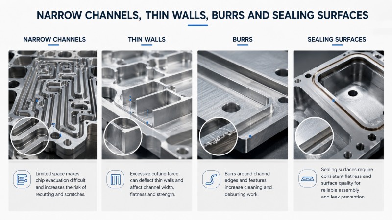
Cold plates and distribution blocks may contain narrow slots, curved channels, closely spaced paths, or repeated internal features. Limited space around the cutter makes chip evacuation more difficult, especially when the channel becomes deeper.
If chips remain inside the channel, they may be cut again by the tool. This can scratch the bottom surface, damage the sidewall, increase cutting heat, and place additional load on a small-diameter end mill.
Thin Walls Between Channels
Closely spaced channels may leave thin walls between adjacent flow paths. Excessive cutting force can deflect these walls, change the channel width, or reduce the flatness of the entire plate.
A low cutting-force geometry, controlled radial engagement, balanced machining sequence, and stable workholding are important when machining thin cold plate structures.
Burrs Around Channel Edges
Burrs may form around channel entrances, exits, thin edges, connector features, and the top surface of a cold plate. They increase cleaning and deburring work and may interfere with later assembly, joining, or sealing operations.
Burr formation is influenced by tool sharpness, cutting direction, feed per tooth, workpiece support, tool wear, and the way the cutter exits the material.
High Requirements for Sealing Surfaces
The surfaces used for covers, gaskets, connectors, or mating parts must remain consistent. Visible tool marks, local steps, remaining burrs, and flatness errors can make later assembly and sealing more difficult.
Finishing these areas requires low runout, a stable cutting edge, controlled allowance, and a toolpath that avoids sudden changes in engagement.
Select the End Mill According to the Workpiece Material
Liquid cooling components can be made from aluminum alloys, stainless steel, copper alloys, and other engineering materials. The correct end mill should be chosen according to the actual workpiece material rather than the component name alone.
| Workpiece Material | Typical Liquid Cooling Parts | Main Machining Risk | End Mill Priority |
|---|
| Aluminum alloy | Cold plates, housings, covers, and distribution blocks | Built-up edge, chip packing, burrs, and thin-wall deformation | Sharp cutting edge, large chip space, polished flute, and low cutting resistance |
| Stainless steel | Manifolds, connector blocks, valve parts, and mounting components | Heat accumulation, work hardening, vibration, and tool wear | Strong edge support, wear-resistant coating, chip evacuation, and vibration control |
| Copper or copper alloy | Heat-transfer plates and local cooling components | Material adhesion, burrs, scratching, and unstable chip formation | Sharp edge, smooth flute, low runout, and controlled engagement |
End Mills for Aluminum Liquid Cooling Plates
Aluminum is widely used for lightweight cooling plates, housings, and distribution components. It can be machined at high speed, but an unsuitable cutter may cause material adhesion, built-up edge, burr formation, or chip packing inside narrow channels.
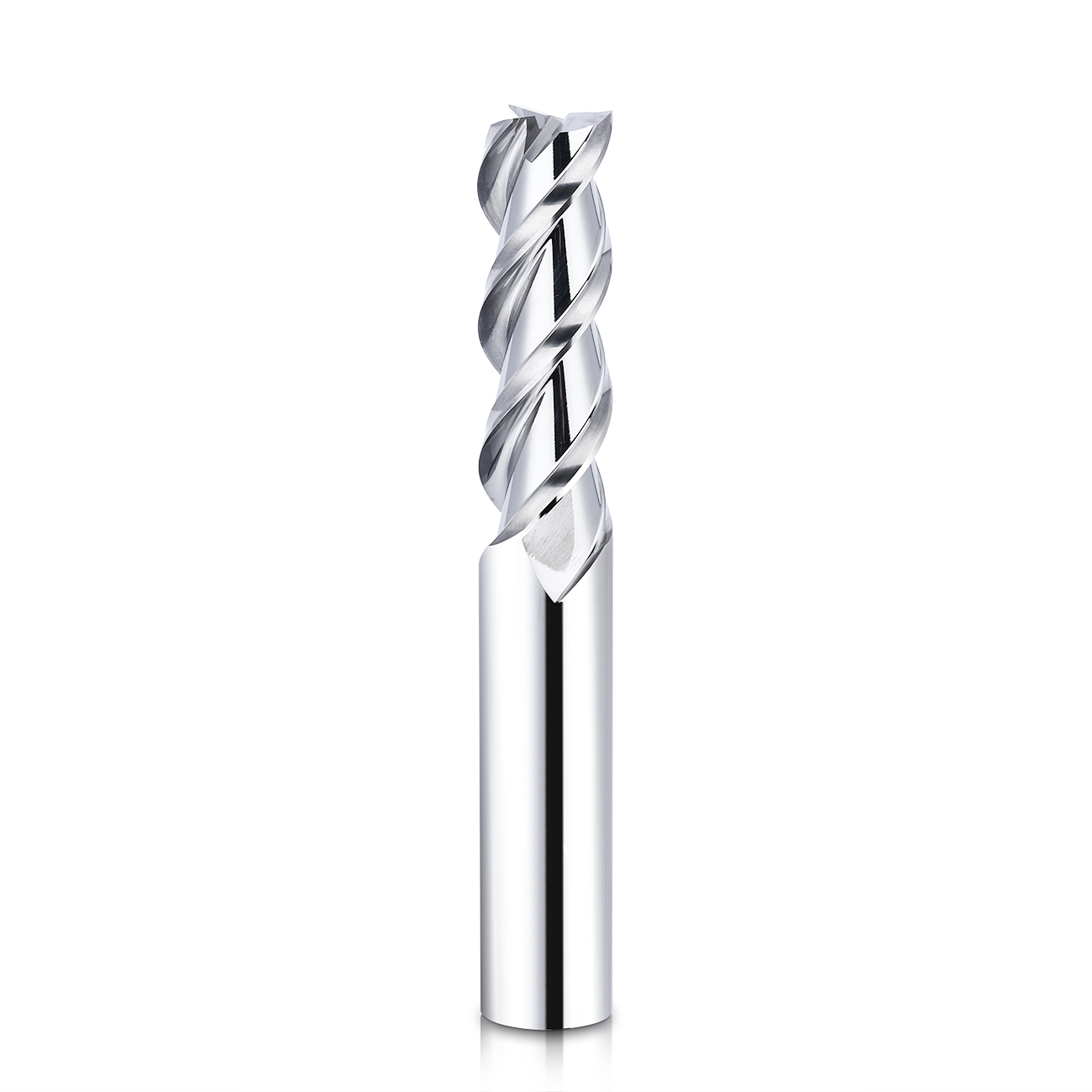
An aluminum end mill should provide enough chip space to remove material from the channel before it is cut again. Sharp cutting edges help reduce cutting pressure, while smooth or polished flutes support chip movement and reduce material adhesion.
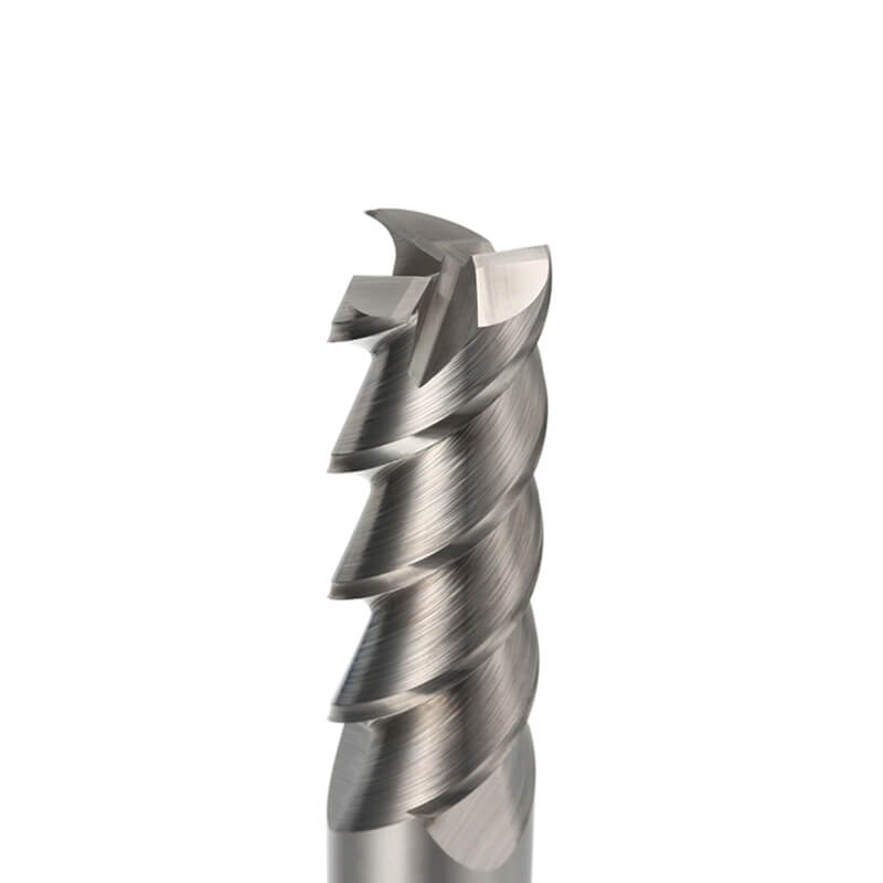
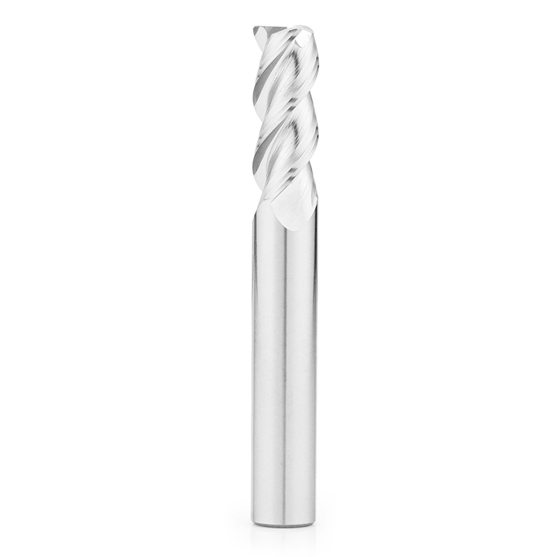
Dohre AEX aluminum end mills are designed with sharp cutting edges, polished flutes, and aluminum-oriented geometry for slotting, pocket machining, side milling, contouring, and surface finishing.
For a cold plate, the cutter diameter and flute length should match the channel width and depth without creating unnecessary overhang. A cutter that is much longer than the feature requires will be more sensitive to deflection and vibration.
End Mills for Stainless-Steel Manifolds and Distribution Blocks
Stainless steel may be used for manifolds, rack connections, valve components, brackets, connector blocks, and parts exposed to demanding coolant or operating conditions.
Compared with aluminum, stainless steel creates more cutting heat and places higher demands on tool wear resistance and cutting stability. Rubbing or repeated passes over a work-hardened surface can accelerate edge wear and reduce dimensional consistency.
Dohre TEX stainless steel end mills use optimized geometry for chip evacuation and unequal flute design for vibration control. They are suitable for slots, pockets, sidewalls, cavities, and semi-finishing operations in stainless-steel cooling components.
When machining a manifold, avoid leaving the tool rubbing at the bottom of a pocket or in a corner. Smooth entry paths, stable engagement, and controlled cutting load help protect the cutting edge and improve the consistency of ports and sealing features.
Small-Diameter End Mills for Narrow Cooling Channels
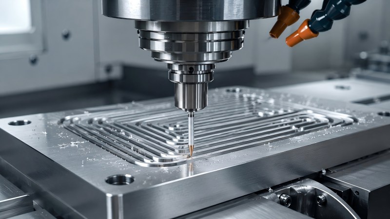
Narrow channels, small slots, connector details, and compact cavities may require a small-diameter end mill. As the cutter diameter decreases, tool rigidity and chip space also become more limited.
The machining process should therefore reduce sudden tool engagement and avoid excessive axial depth. Chip removal becomes especially important because even a small amount of packed material can increase cutting force and damage a micro cutting edge.
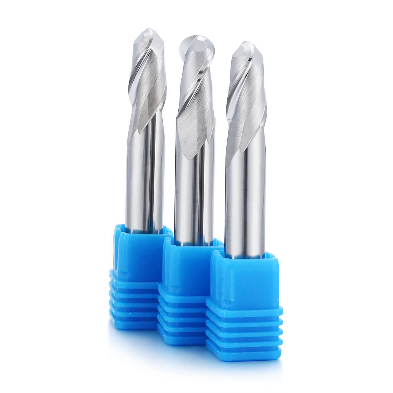
A solid carbide micro-diameter end mill can be used for narrow slots, small features, fine profiles, and precision details where a standard-diameter cutter cannot reach.
Tool runout should be checked before machining. With a micro end mill, a small amount of runout can cause one flute to carry most of the load, leading to rapid wear, oversize channels, poor sidewalls, or sudden tool breakage.
Machining Workflow for Liquid Cooling Plates
A stable machining process usually separates material removal, channel formation, and final surface finishing. Trying to complete every feature with one cutter and one cutting strategy may reduce control over channel accuracy and sealing-surface quality.
| Machining Stage | Main Objective | Tool Selection Priority |
|---|
| Main cavity roughing | Remove bulk material efficiently | Tool rigidity, chip space, and stable material removal |
| Flow-channel milling | Create the required channel width, depth, and path | Correct diameter, limited overhang, chip evacuation, and low runout |
| Semi-finishing | Correct sidewalls and leave a uniform finishing allowance | Stable engagement, dimensional control, and predictable tool wear |
| Sealing-surface finishing | Reach the required flatness and surface condition | Sharp and stable edge, low runout, and controlled step-over |
| Edge finishing | Reduce burrs around channels, ports, and external edges | Accurate toolpath, suitable edge geometry, and controlled exit cutting |
How to Improve Chip Evacuation in Narrow Flow Channels
Chip evacuation becomes more difficult as a channel becomes narrower or deeper. Chips trapped between the cutter and channel wall can create scratches, increase heat, and change the effective cutting load.
• Select a cutter with enough flute space for the workpiece material.
• Avoid excessive cutting depth when the channel does not allow chips to escape easily.
• Use suitable coolant, air, or chip-flushing direction according to the material and machine setup.
• Do not allow chips from a previous pass to remain inside the next cutting path.
• Use layered or progressive machining when full-depth engagement would overload the cutter.
Chip evacuation should be considered together with flute count. More flutes can provide additional cutting edges and tool core strength, but they also reduce the space available for chips. The correct balance depends on material, cutter diameter, and channel engagement.
How to Reduce Burrs Around Cooling Channels
Burrs are not always solved by reducing feed. A worn cutting edge, unsupported thin wall, incorrect cutting direction, or unstable tool exit can continue producing burrs even at a lower feed rate.
Begin by checking the edge condition and the location of the burr. Burrs concentrated at the channel exit may indicate that the final cutting direction or toolpath transition should be changed. Burrs along an entire edge may indicate wear, deflection, or unsuitable tool geometry.
• Use a sharp cutter designed for the workpiece material.
• Replace the tool before heavy edge wear affects the channel boundary.
• Support thin walls and avoid cutting them with excessive radial load.
• Control tool entry and exit instead of allowing an abrupt breakout.
• Use a separate light finishing pass when channel-edge quality is critical.
How to Control Thin-Wall Deformation and Plate Flatness
Removing a large amount of material from one area can release internal stress or create an unbalanced cutting load. This is especially important for lightweight cold plates with closely spaced channels and thin remaining walls.
Instead of cutting one side completely before moving to the next, a balanced machining sequence can distribute material removal more evenly. Roughing and finishing should also be separated so that the final pass removes a controlled amount of material.
Workholding should support the component without distorting it. Excessive clamping force may temporarily hold the plate flat during machining but allow it to move after release. The clamping position, cutting sequence, and remaining wall structure should be considered together.
Finishing Sealing Surfaces and Mating Areas
Sealing surfaces require a different priority from rough channel machining. The main objective is no longer maximum material removal but stable flatness, consistent tool marks, clean edges, and controlled dimensions.
Before the finishing pass, check tool runout, cutting-edge wear, holder cleanliness, remaining allowance, and workpiece support. A damaged edge or unstable holder can leave visible marks across the entire sealing area.
A consistent finishing allowance helps every flute experience a similar cutting load. If the previous operation leaves uneven stock, the finishing tool may deflect differently across the surface and create local dimensional variation.
Tool Runout and Overhang in Precision Channel Milling
Runout causes the cutting edges to remove different amounts of material. One flute may carry most of the load while the other flutes cut less or rub against the surface.
The result may include unequal tool wear, inconsistent channel width, visible sidewall marks, increased burr formation, and shorter tool life. The problem becomes more serious as the cutter diameter decreases.
Use the shortest practical tool overhang and keep the holder, collet, and spindle interface clean. A long-reach tool should only be used when the component geometry requires it, and cutting conditions should be adjusted for the reduced rigidity.
Custom End Mills for Special Liquid Cooling Features
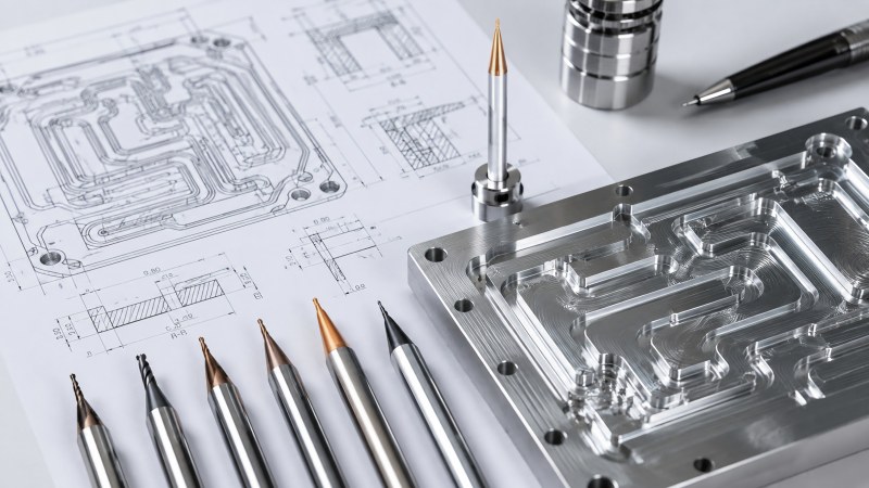
Standard end mills can machine many cold plate and manifold features, but some designs require unusual channel widths, long-reach geometries, special corner radii, stepped profiles, or multiple dimensions in one operation.
In these cases, a custom tool can match the feature more closely and reduce unnecessary tool changes. Tool diameter, neck length, flute length, corner form, coating, and cutting geometry can be selected around the drawing and workpiece material.
Dohre provides custom and non-standard milling tools for special profiles, deep grooves, long-reach features, micro structures, and application-specific machining requirements.
Practical Checklist for Liquid Cooling Component Milling
• Confirm whether the workpiece is aluminum, stainless steel, copper alloy, or another material.
• Select the cutter diameter according to the actual channel width and corner requirement.
• Use the shortest flute and tool overhang that can reach the feature.
• Check runout before machining narrow channels or small features.
• Provide enough chip space and chip flushing for deep slots and cavities.
• Avoid sudden entry or exit near thin channel walls.
• Separate roughing, semi-finishing, and sealing-surface finishing when accuracy is important.
• Inspect tool wear before the final channel or surface-finishing operation.
• Use a balanced machining sequence to reduce plate distortion.
• Evaluate burrs, flatness, channel dimensions, and surface finish as part of the complete process.
FAQ
What type of end mill is suitable for an aluminum liquid cooling plate?
An aluminum-oriented end mill with sharp cutting edges, enough chip space, low cutting resistance, and smooth or polished flutes is generally suitable. The diameter and flute length should also match the channel dimensions.
Why do chips become trapped inside liquid cooling channels?
Narrow channel width, excessive cutting depth, limited flute space, poor flushing direction, and deep engagement can prevent chips from leaving the cutting area. Trapped chips may then be recut by the end mill.
Can the same end mill machine aluminum cold plates and stainless-steel manifolds?
It is not recommended as a general approach. Aluminum and stainless steel have different chip formation, heat, adhesion, and edge-strength requirements. A cutter designed for the specific workpiece material usually provides more stable performance.
How can burrs around cooling channels be reduced?
Use a sharp and suitable cutting edge, control tool wear, support thin walls, optimize the cutting direction, and avoid an unstable exit from the material. A light finishing pass may also improve channel-edge quality.
Why is runout important when using a small-diameter end mill?
Runout creates unequal flute loading. On a small cutter, even a small amount can concentrate most of the cutting force on one edge, causing rapid wear, dimensional error, poor surface quality, or tool breakage.
When is a custom end mill needed for a liquid cooling component?
A custom tool may be useful when the component contains a special channel width, unusual profile, deep narrow feature, extended reach, combined step, or production operation that cannot be completed efficiently with a standard cutter.
Conclusion
Machining server liquid cooling components involves more than cutting a cavity or slot. Flow-channel accuracy, chip evacuation, burr control, thin-wall stability, sealing-surface quality, and tool consistency all influence the finished component.
The end mill should be selected according to the workpiece material and the actual feature. Aluminum cold plates benefit from sharp edges and efficient chip evacuation, while stainless-steel manifolds require stronger edge support, wear resistance, and vibration control. Small channels also require careful control of runout, overhang, and chip removal.
Dohre provides carbide end mills for aluminum, stainless steel, micro-feature machining, and other precision manufacturing applications. Standard and custom tool solutions can be selected according to the component drawing, workpiece material, channel dimensions, tolerance, and production requirements. Contact us for liquid cooling plate and manifold machining tool recommendations.