How to Machine Narrow Flow Channels in Server Cold Plates
Introduction
Narrow flow channels place high demands on end mill rigidity, chip evacuation, runout control, and cutting stability. The correct tool should be selected according to the channel width, depth, corner radius, workpiece material, wall thickness, and required surface quality.
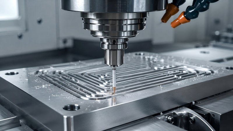
Narrow flow channels are important features in many server cold plate designs. They guide coolant through the plate and increase the contact area available for heat transfer, but they also create demanding conditions for CNC milling.
As the channel becomes narrower or deeper, the end mill becomes less rigid and chips have less space to leave the cutting area. Excessive runout, long tool overhang, unsuitable flute geometry, or poor chip evacuation can lead to dimensional error, scratched channel walls, burrs, rapid tool wear, or sudden cutter breakage.
This article focuses on cold plate channels that are produced or finished by CNC end milling. The correct machining method depends on the actual channel geometry, workpiece material, wall thickness, surface requirement, machine condition, and production volume.
Why Narrow Cold Plate Channels Are Difficult to Mill
A narrow channel limits both cutter diameter and flute space. The tool must be small enough to produce the required width and internal radius, but it must also remain rigid enough to resist deflection during slotting and side milling.
Chip evacuation becomes more difficult because the surrounding walls restrict coolant, air, and chip movement. Chips that remain in the channel may be cut again, increasing heat and leaving scratches on the bottom or sidewall.
The channel may also be surrounded by thin walls. Excessive radial force can move these walls during machining, changing the final channel width or reducing plate flatness after the workpiece is released from the fixture.
| Channel Condition | Main Machining Risk | Process Priority |
|---|
| Narrow channel width | Small cutter diameter and reduced rigidity | Use the largest tool that fits the required width and radius |
| Deep channel | Long reach, deflection, vibration, and poor chip removal | Limit overhang and use progressive cutting depth |
| Closely spaced channels | Thin-wall movement and plate distortion | Control cutting force and balance the machining sequence |
| Small internal radius | Requires a smaller cutter than the main channel | Rough with a larger tool and finish remaining corners separately |
| Long continuous toolpath | Tool wear, chip accumulation, and dimensional drift | Monitor edge condition and maintain consistent chip evacuation |
Confirm the Channel Geometry Before Selecting the End Mill
Tool selection should begin with the component drawing. Channel width alone is not enough. The depth, internal corner radius, wall thickness, channel path, entry position, bottom shape, and available clearance all affect the required cutter.
A cutter may fit the nominal channel width but still be unsuitable if the flute is too short, the neck cannot clear the surrounding wall, or the holder interferes with the workpiece. Conversely, selecting an unnecessarily long cutter reduces rigidity and makes the process more sensitive to vibration and runout.
| Drawing Information | Why It Matters |
|---|
| Channel width | Determines the maximum cutter diameter |
| Channel depth | Determines the required cutting length and reach |
| Internal radius | May require a smaller finishing cutter than the main roughing tool |
| Wall thickness | Affects allowable cutting force and machining sequence |
| Access and surrounding geometry | Determines whether a reduced neck or custom reach is required |
| Tolerance and surface requirement | Determines whether roughing and finishing should use separate tools |
Use the Largest Cutter Diameter That Fits the Channel
A smaller cutter is not automatically more accurate. Reducing the diameter also reduces the tool core and increases sensitivity to bending, runout, and chip congestion.
Where the channel geometry allows, use the largest cutter diameter that can produce the required width and internal radius. A larger tool generally provides better rigidity, greater resistance to deflection, and more stable sidewall control.
When the channel contains small corner radii, one practical approach is to rough most of the material with a larger end mill and use a smaller cutter only for the remaining corners or detailed areas. This reduces the time that the weakest tool spends under heavy cutting load.
Match Cutting Length and Neck Length to the Actual Depth
Cutting length, neck length, and total overhang should not be treated as the same measurement. Each one affects the tool differently.
• Cutting length should cover the material that the flute must actually machine.
• Neck length provides clearance around deeper channel walls or surrounding structures.
• Tool overhang is the unsupported length extending from the holder and should remain as short as possible.
An unnecessarily long flute weakens the cutter along the entire cutting section. For a deep channel, a short cutting edge with a properly designed reduced neck may provide better rigidity than a long full-flute tool.
The shortest catalog tool that safely reaches the feature is generally preferable. When a standard cutter requires excessive extension, a custom neck length may provide a more stable solution.
Choose Flute Count According to Material and Chip Space
Flute count affects both chip evacuation and tool-core strength. Fewer flutes usually provide more open space for chips, while additional flutes can increase the number of cutting edges and strengthen the core in some designs.
For aluminum channels, generous chip space and polished flutes are important because long chips and built-up edge can block narrow passages. For copper channels, smooth flute surfaces and a sharp cutting edge help reduce adhesion and prevent chips from smearing along the channel.
The correct flute count should be selected according to the workpiece material, cutter diameter, full-slot engagement, spindle capability, and evacuation method. A flute configuration that performs well in side milling may not be ideal for a deep full-width slot.
Copper and Aluminum Channels Require Different Priorities
Copper and aluminum cold plates may contain similar channel structures, but their cutting behavior is different. The tool should be matched to the actual alloy rather than selected only from the channel dimensions.
| Machining Factor | Aluminum Channel | Copper Channel |
|---|
| Common chip problem | Long chips, packing, and built-up edge | Adhesion, smearing, and chip recutting |
| Cutting-edge priority | Sharp edge with low cutting resistance | Very sharp edge for clean shearing |
| Flute priority | Large chip space and polished evacuation path | Smooth flute and controlled chip movement |
| Surface concern | Built-up edge, burrs, and thin-wall movement | Scratches, smearing, and fine residual burrs |
| Setup priority | Low cutting force and effective chip flushing | Low runout and prevention of chip recutting |
A more detailed comparison is available in our guide to copper versus aluminum server cold plate machining and end mill selection.
Avoid Full-Depth Cutting When Chip Space Is Limited
A deep full-width slot places cutting load on both sides of the end mill while limiting the path available for chips to escape. On a small-diameter cutter, this can quickly lead to heat, chip packing, deflection, or breakage.
Progressive depth or layered machining is usually more stable when the channel is deep relative to the cutter diameter. Each pass removes a controlled amount of material and allows chips to be cleared before the next layer begins.
The exact depth per pass should follow the material, tool diameter, flute geometry, machine rigidity, holder, and coolant condition. A fixed value should not be applied to every channel or material.
Use a Stable Entry Strategy
Sudden vertical entry or immediate full-width engagement can overload a small cutter. The entry method should place the cutting edge into the material gradually and maintain chip evacuation from the beginning of the operation.
Depending on the component and tool capability, a ramp, helical entry, pre-machined entry pocket, or progressive side entry may provide a smoother start than direct plunging. The selected method should be compatible with the end mill geometry.
Entry and exit positions should also avoid unsupported thin walls where possible. Breaking out through a weak edge can create burrs or move the channel wall.
Improve Chip Evacuation Before Increasing Cutting Speed
When chips remain inside the flow channel, increasing spindle speed alone will not solve the problem. More chips may be generated while the evacuation path remains restricted.
• Use a cutter with enough flute space for the workpiece material.
• Direct coolant or air toward the cutting area rather than across the top of the plate.
• Clear chips between progressive depth passes.
• Avoid allowing chips from one channel to enter a nearby finished channel.
• Keep the flute and cutting edge free from built-up material.
• Use a machining sequence that keeps the evacuation path open.
Chip evacuation should be evaluated by inspecting the channel surface and the chips themselves. Scratches, welded material, unexpected heat, and irregular chip shape may indicate that material is being recut.
Why Runout Is Critical for Small-Diameter Channel Milling
Runout causes the cutting edges to remove unequal amounts of material. One flute may carry most of the cutting load while another flute cuts very little or rubs against the channel surface.
On a small-diameter end mill, even a small runout value represents a significant percentage of the tool diameter. The result may include an oversized channel, unequal sidewalls, rapid edge wear, burr growth, or sudden tool failure.
Before machining, inspect the holder, collet, spindle interface, tool clamping length, and cleanliness of all contact surfaces. Runout should be checked close to the cutting edge rather than only on the shank.
Control Tool Overhang and Holder Interference
The cutter should extend only far enough to reach the deepest point of the channel while maintaining safe clearance from the holder. Additional extension increases bending and makes the tool more sensitive to vibration.
A long-neck cutter may be necessary when the channel is surrounded by raised walls or other features, but the neck should not be longer than required. Holder shape and spindle access should be reviewed together with the cutter design.
When the holder is the main source of interference, changing to a slimmer holder or custom tool geometry may provide better rigidity than simply extending a standard cutter farther from the holder.
Protect Thin Walls Between Adjacent Channels
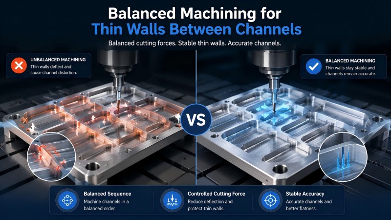
Closely spaced flow channels may leave narrow walls that can move during machining. If one side is fully machined while the opposite side still contains solid material, cutting pressure may push the wall away from the tool.
A balanced sequence can reduce this effect. Rough neighboring channels progressively rather than completing one channel entirely before beginning the next. Leave a controlled amount of material for semi-finishing and finish both sides under similar cutting conditions.
Clamping force must also be controlled. Excessive pressure may hold the plate flat during machining but allow it to distort after unclamping.
Separate Channel Roughing and Finishing
Roughing and finishing have different priorities. Roughing focuses on stable material removal and chip evacuation, while finishing focuses on final channel width, wall quality, burr control, and surface consistency.
| Machining Stage | Main Objective | Process Priority |
|---|
| Channel roughing | Remove material without overloading the cutter | Chip evacuation, progressive depth, and stable entry |
| Semi-finishing | Correct wall shape and leave uniform stock | Balanced engagement and controlled wall movement |
| Channel finishing | Reach final width, edge quality, and surface condition | Sharp edge, low runout, light engagement, and clean channel |
| Final inspection | Confirm dimensions and remove residual chips or burrs | Channel width, depth, wall condition, burrs, and cleanliness |
A heavily worn roughing cutter should not be used for the final pass when channel tolerance or surface quality is important. A separate finishing tool can provide more predictable edge condition and dimensional control.
Monitor Tool Wear Before the Channel Becomes Oversized
Tool wear may first appear as a change in channel quality rather than complete cutter failure. Common warning signs include increasing burrs, wider slots, uneven sidewalls, more spindle load, surface scratches, or a change in chip shape.
In repeated production, tool life should be controlled according to the first feature that becomes unacceptable. This may be channel width, bottom finish, wall position, burr height, or cutting-edge condition.
Tool-life records should include material grade, cutter diameter, channel depth, holder, overhang, cutting data, and inspection results. This helps distinguish normal wear from problems caused by runout, chip congestion, or workholding.
When Is a Custom End Mill Needed?
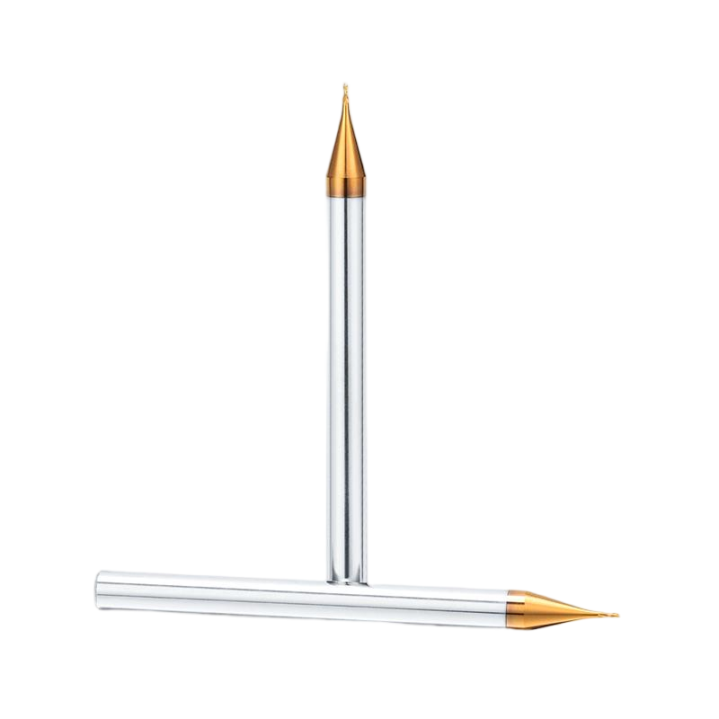
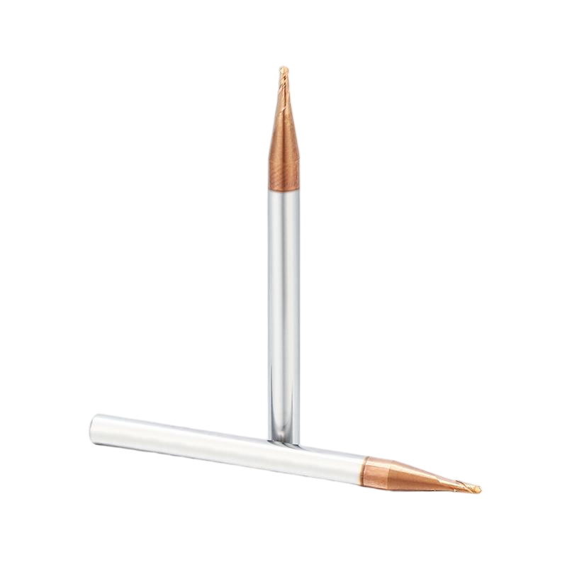
Standard small-diameter end mills can machine many cooling channels, but some designs require a combination of diameter, cutting length, neck clearance, corner form, and overall length that is not available in a standard catalog tool.
A custom end mill may be useful when the component contains:
• A non-standard channel width.
• A deep channel requiring a short flute and long reduced neck.
• A special bottom radius or sidewall transition.
• A stepped channel or combined profile.
• Restricted holder clearance.
• A material requiring application-specific edge or flute geometry.
Dohre provides custom and non-standard end mills according to the channel drawing, workpiece material, cutting depth, neck clearance, corner requirement, tolerance, and machine conditions.
Practical Checklist for Narrow Flow Channel Milling
• Confirm the workpiece material and alloy before selecting the cutter.
• Check channel width, depth, corner radius, and surrounding clearance.
• Use the largest cutter diameter that fits the required geometry.
• Match cutting length to the actual depth of material engagement.
• Use only the neck length required for feature clearance.
• Keep total tool overhang as short as possible.
• Select flute count according to material, slot engagement, and chip space.
• Use progressive depth when full-depth cutting restricts chip evacuation.
• Direct coolant or air into the cutting area and clear chips between passes.
• Check runout near the cutting edge before using a small-diameter tool.
• Use a balanced sequence when machining thin walls between channels.
• Separate roughing and finishing when channel tolerance is critical.
• Monitor burrs, channel width, surface scratches, and tool wear during production.
• Consider a custom tool when a standard cutter requires excessive reach or cannot match the feature.
FAQ
What type of end mill is suitable for narrow cold plate channels?
A small-diameter carbide end mill with the correct material-specific geometry, sufficient chip space, low runout, and only the required cutting and neck length is generally suitable. The exact tool depends on the channel and workpiece material.
Should the smallest possible cutter be used for a narrow channel?
No. Use the largest cutter that can produce the required channel width and internal radius. A larger diameter usually provides better rigidity and dimensional stability.
Why do small end mills break during cold plate channel milling?
Common causes include excessive runout, long overhang, deep full-width cutting, chip packing, unsuitable entry, sudden engagement, poor material matching, and worn cutting edges.
How can chips be removed from deep narrow channels?
Use sufficient flute space, progressive depth, suitable coolant or air direction, and regular chip clearing between passes. The machining sequence should keep the evacuation path open.
Can the same end mill machine copper and aluminum channels?
It may be possible in some operations, but it is not recommended as a general solution. Aluminum and copper have different adhesion, chip-flow, burr, and edge-sharpness requirements.
When is a reduced-neck end mill needed?
A reduced-neck tool is useful when the cutting edge must reach a deep channel while the non-cutting section needs clearance from surrounding walls. The neck should be no longer than required.
When should a custom end mill be considered?
A custom cutter may be appropriate for non-standard widths, deep channels, special radii, stepped profiles, limited holder clearance, or applications where standard tools require excessive extension.
Conclusion
Narrow flow channel milling requires a balance between tool access, rigidity, chip evacuation, and dimensional control. Selecting a cutter only by channel width can lead to unnecessary overhang, insufficient flute space, or poor clearance around the feature.
The most stable process uses the largest suitable cutter diameter, the shortest practical cutting and neck length, low runout, progressive cutting depth, and a chip-removal method matched to the channel and material. Copper and aluminum also require different priorities for edge sharpness, adhesion control, burr reduction, and surface protection.
Dohre provides solid carbide micro-diameter end mills, aluminum-specific tools, and custom milling solutions for narrow channels, long-reach features, special radii, and precision liquid cooling components. Contact us with your material, channel width, depth, corner radius, tolerance, and machine conditions for tool recommendations.