





Choosing the right carbide insert requires more than matching an insert to a toolholder. Machining operation, workpiece material, insert geometry, carbide grade, nose radius, cutting conditions, and surface finish requirements all influence insert performance.
A suitable insert can improve chip control, cutting stability, tool life, and surface quality, while an unsuitable selection may lead to excessive wear, vibration, poor chip formation, or premature edge failure.
This guide explains the main factors to consider when selecting carbide inserts for turning, milling, finishing, roughing, and other indexable machining applications.
What Is a Carbide Insert?
A carbide insert is a replaceable cutting element used in indexable cutting tools. Unlike solid cutting tools, the insert can be replaced or indexed when the cutting edge becomes worn, while the toolholder remains in use.
Carbide inserts are commonly used for turning, milling, grooving, parting, threading, and other machining operations. They are available in different shapes, geometries, carbide grades, coatings, sizes, and nose radii to suit different workpiece materials and cutting conditions.
Key Factors in Carbide Insert Selection
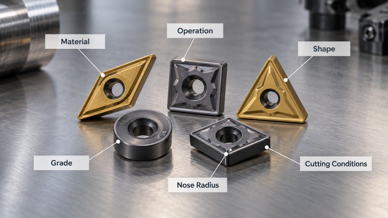
Before choosing an insert, consider the machining application as a complete system rather than focusing on only one parameter.
| Selection Factor | What to Consider |
|---|---|
| Machining Operation | Turning, milling, finishing, roughing, grooving, or threading |
| Workpiece Material | Steel, stainless steel, cast iron, non-ferrous materials, heat-resistant alloys, or hardened materials |
| Insert Geometry | Positive or negative geometry, cutting edge strength, and chipbreaker design |
| Insert Shape | Edge strength, accessibility, entering angle, and machining profile |
| Carbide Grade | Balance between wear resistance and toughness |
| Nose Radius | Cutting force, edge strength, feed capability, and surface finish |
| Cutting Conditions | Cutting speed, feed rate, depth of cut, coolant, and interrupted cutting |
| Machine Rigidity | Machine condition, workholding stability, tool overhang, and vibration risk |
1. Select the Insert According to the Machining Operation
The first step is to identify the machining operation. Inserts designed for finishing, roughing, turning, or milling have different cutting edge requirements.
Turning
Turning inserts are selected according to the type of turning operation, workpiece material, cutting direction, depth of cut, and required surface finish. Stable external turning may allow stronger cutting edges and higher cutting loads, while internal turning or slender workpieces may require lower cutting forces.
Finishing
Finishing operations normally involve smaller depths of cut and lower material removal rates. Inserts with sharp cutting geometry and suitable chip control can help reduce cutting forces and improve surface quality.
For fine finishing, insert selection should also consider machine rigidity, workpiece stability, feed rate, and nose radius. A sharper edge may improve cutting performance, but excessive edge sharpness can reduce cutting edge strength in demanding conditions.
Roughing
Roughing removes larger amounts of material and usually creates higher cutting forces. A stronger cutting edge, robust insert geometry, and tougher carbide grade are generally more important than achieving the finest possible surface finish.
Interrupted cuts, scale, unstable workholding, or variable cutting depths may require additional edge strength and toughness.
Milling
Indexable milling inserts repeatedly enter and leave the cut, creating cyclic mechanical and thermal loads. Milling insert selection therefore depends heavily on edge toughness, cutter geometry, workpiece material, and machining stability.
How to Choose a Carbide Insert for Lathe Finishing
Lathe finishing is one of the applications where insert geometry and nose radius can have a direct influence on surface finish.
For finishing operations, engineers generally look for an insert that can produce stable cutting at relatively light depths of cut while maintaining good chip control. Positive cutting geometry can help reduce cutting force, especially on smaller parts, thin-walled components, or less rigid setups.
Nose radius should be matched to the feed rate and machine rigidity. A smaller nose radius can reduce cutting forces and may help in light finishing operations, while a larger nose radius provides a stronger cutting edge and can support higher feeds when the machining setup is sufficiently rigid.
Surface finish also depends on tool condition, machine vibration, workpiece clamping, cutting parameters, and material characteristics. Insert selection should therefore be evaluated together with the complete machining setup.
2. Choose the Insert Based on Workpiece Material
Workpiece material is one of the most important factors in carbide insert selection because different materials generate different cutting temperatures, cutting forces, chip forms, and tool wear mechanisms.
The ISO workpiece material groups commonly used in cutting tool selection are:
• P – Steel
• M – Stainless steel
• K – Cast iron
• N – Non-ferrous materials
• S – Heat-resistant alloys and titanium alloys
• H – Hardened materials
Each group requires a different balance of cutting edge strength, carbide grade, coating, and geometry. For a more detailed explanation of these material groups, see our P M K N S H carbide insert material classification guide.
3. Understand the Main Types of Carbide Inserts
Carbide inserts can also be classified according to their machining function. Understanding the application type helps narrow down the selection before considering specific geometry or grade.
Turning Inserts
Turning inserts are used for external turning, internal turning, facing, profiling, and other lathe operations. Shape, clearance angle, chipbreaker, nose radius, and grade are selected according to the workpiece and machining conditions.
Milling Inserts
Milling inserts are used in indexable milling cutters for face milling, shoulder milling, profile milling, and other operations. Because milling involves repeated entry into and exit from the workpiece, edge toughness and cutter stability are especially important.
Grooving and Parting Inserts
These inserts are designed for narrow cutting widths and controlled radial or axial cutting. Insert width, cutting edge strength, chip evacuation, and toolholder rigidity are important selection factors.
Threading Inserts
Threading inserts use specific profiles to generate thread forms. Selection depends on thread standard, pitch, internal or external threading, workpiece material, and cutting direction.
4. Select the Right Insert Shape
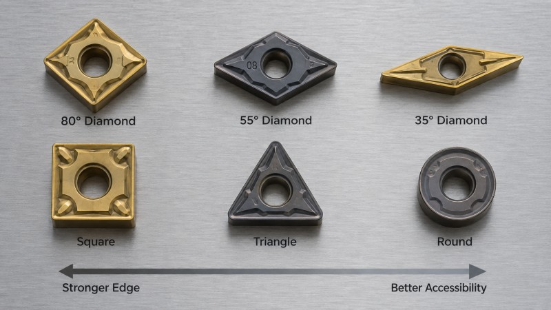
Insert shape influences cutting edge strength, accessibility, entering angle, and the types of profiles that can be machined.
Shapes with larger included angles generally provide stronger cutting edges and are suitable for applications where edge strength is important. More pointed insert shapes provide improved accessibility for profiling and contouring but normally have less cutting edge strength.
Common carbide insert shapes include diamond, triangular, square, round, and other application-specific geometries.
For example, an 80-degree diamond insert provides relatively high edge strength and is widely used in general turning, while smaller included-angle diamond inserts provide better access for profiling and complex contours.
Round inserts provide high edge strength and distribute cutting forces over a larger edge area, making them useful for certain profiling and demanding cutting applications.
5. Choose the Insert Grade and Coating
Carbide grade selection requires balancing wear resistance and toughness.
A harder grade may provide better wear resistance under stable machining conditions, while a tougher grade may be more suitable for interrupted cutting, unstable setups, or applications where the cutting edge experiences higher mechanical impact.
Coating selection should also follow the workpiece material and cutting conditions. Coatings can improve wear resistance, heat resistance, and cutting performance, but the most suitable coating depends on the application rather than simply choosing the hardest available option.
When selecting a grade, consider cutting speed, feed rate, depth of cut, workpiece hardness, coolant conditions, and whether the cut is continuous or interrupted.
6. Select the Appropriate Nose Radius
Nose radius affects cutting edge strength, cutting force, feed capability, vibration tendency, and surface finish.
Larger Nose Radius
A larger nose radius generally provides a stronger cutting edge and can support higher feed rates under stable machining conditions. However, it also produces higher radial cutting forces and may increase vibration on slender workpieces or less rigid setups.
Smaller Nose Radius
A smaller nose radius generally produces lower cutting forces and can be useful for light finishing, smaller components, or applications with limited machine rigidity. However, the cutting edge is less robust and may require more conservative cutting conditions.
The correct nose radius should therefore be selected according to feed rate, depth of cut, workpiece stability, and required surface finish rather than choosing the largest or smallest radius automatically.
7. How to Identify a Carbide Insert
Carbide inserts often use standardized designation systems that describe important dimensional and geometric characteristics.
An insert designation may contain information about:
• Insert shape
• Clearance angle
• Tolerance class
• Insert type or fixing method
• Insert size
• Thickness
• Nose radius
Understanding these codes helps engineers determine whether an insert is physically compatible with a toolholder and whether its geometry is suitable for the intended machining operation.
However, the designation alone does not determine the complete cutting performance. Carbide grade, coating, chipbreaker geometry, workpiece material, and cutting parameters must also be considered.
8. Consider Cutting Conditions and Machine Rigidity
Two identical inserts can perform very differently under different machining conditions.
A rigid machine, stable workholding, short tool overhang, and consistent cutting conditions allow more aggressive cutting parameters. In contrast, unstable setups, long overhangs, interrupted cuts, or thin-walled components may require lower cutting forces and tougher cutting edges.
Cutting speed, feed rate, and depth of cut should always be matched to the selected insert grade and geometry. Excessive cutting speed may accelerate thermal wear, while excessive feed or depth of cut can overload the cutting edge.
Coolant application should also be considered according to workpiece material, cutting operation, and tool design.
Common Carbide Insert Selection Mistakes
A common mistake is selecting an insert based on only one factor, such as shape or carbide grade. Reliable insert selection requires matching the insert to the complete machining environment.
Other common mistakes include using an excessively large nose radius on an unstable setup, choosing a grade that is too hard for interrupted cutting, using finishing geometry for heavy roughing, or ignoring workpiece material classification when selecting the insert grade and coating.
If tool life or surface finish is unstable, review the complete combination of insert geometry, grade, cutting parameters, machine rigidity, workholding, and coolant conditions rather than changing only one variable.
Carbide Inserts vs Solid Carbide End Mills
Carbide inserts and solid carbide end mills are both widely used in modern machining, but they serve different applications.
Carbide inserts are mainly used in indexable tooling systems for turning and larger milling applications. Solid carbide end mills are widely used in precision CNC milling, smaller-diameter machining, complex profiles, slots, cavities, and applications that require continuous cutting geometry.
For CNC milling applications, DOHRE focuses on solid carbide end mills for different workpiece materials and machining requirements.
For non-standard milling dimensions, special geometries, or application-specific requirements, DOHRE also provides customized carbide cutting tools for CNC milling applications.
Conclusion
Selecting the right carbide insert requires considering the machining operation, workpiece material, insert shape, geometry, carbide grade, coating, nose radius, cutting parameters, and machine rigidity together.
There is no single insert that is suitable for every application. Finishing, roughing, continuous cutting, interrupted cutting, and different workpiece materials each create different requirements for cutting edge strength, wear resistance, and chip control.
By evaluating these factors systematically, machinists can make more reliable carbide insert selections and achieve more stable tool life, chip control, and surface quality.
If you have a specific CNC milling application or need help selecting a suitable solid carbide tool, you can contact DOHRE to discuss your machining requirements.