Choosing the correct end mill starts with the machining requirement rather than the tool catalog. Two cutters with the same diameter may perform very differently when their end geometry, flute count, cutting length, carbide grade, coating, and tool reach are not designed for the same application.
A suitable end mill should match the workpiece material, feature geometry, machining stage, cutting depth, chip volume, surface-finish target, and machine condition. These factors must be considered together rather than selected independently.
This end mill selection guide explains how manufacturers can narrow down the correct cutter configuration for roughing, semi-finishing, finishing, slotting, side milling, deep cavity machining, three-dimensional contouring, and micro-feature machining.
A Practical End Mill Selection Process
A practical selection process should follow a logical order. Starting with coating or flute count before confirming the material and machining feature can lead to a cutter that looks suitable on paper but does not match the actual cutting conditions.
| Selection Step | Main Question |
|---|
| 1. Workpiece Material | What material and hardness range will be machined? |
| 2. Machining Feature | Is the feature flat, curved, deep, narrow, or three-dimensional? |
| 3. Machining Stage | Is the tool intended for roughing, semi-finishing, or finishing? |
| 4. Flute Count | How much chip space, core strength, and cutting-edge engagement are required? |
| 5. Tool Dimensions | What diameter, cutting length, neck length, and overall reach are necessary? |
| 6. Carbide and Coating | Which substrate, edge preparation, and coating match the material and cutting heat? |
| 7. Machine and Setup | Can the spindle, toolholder, workholding, coolant, and chip evacuation support the tool? |
For a broader explanation of cutter shapes before beginning the selection process, see our guide to common types of end mills and their uses.
Start with the Workpiece Material
Workpiece material affects cutting temperature, chip formation, adhesion, abrasive wear, cutting force, and edge-strength requirements. It therefore influences the carbide substrate, coating, rake angle, helix design, flute space, and cutting-edge preparation.
Aluminum and Copper Alloys
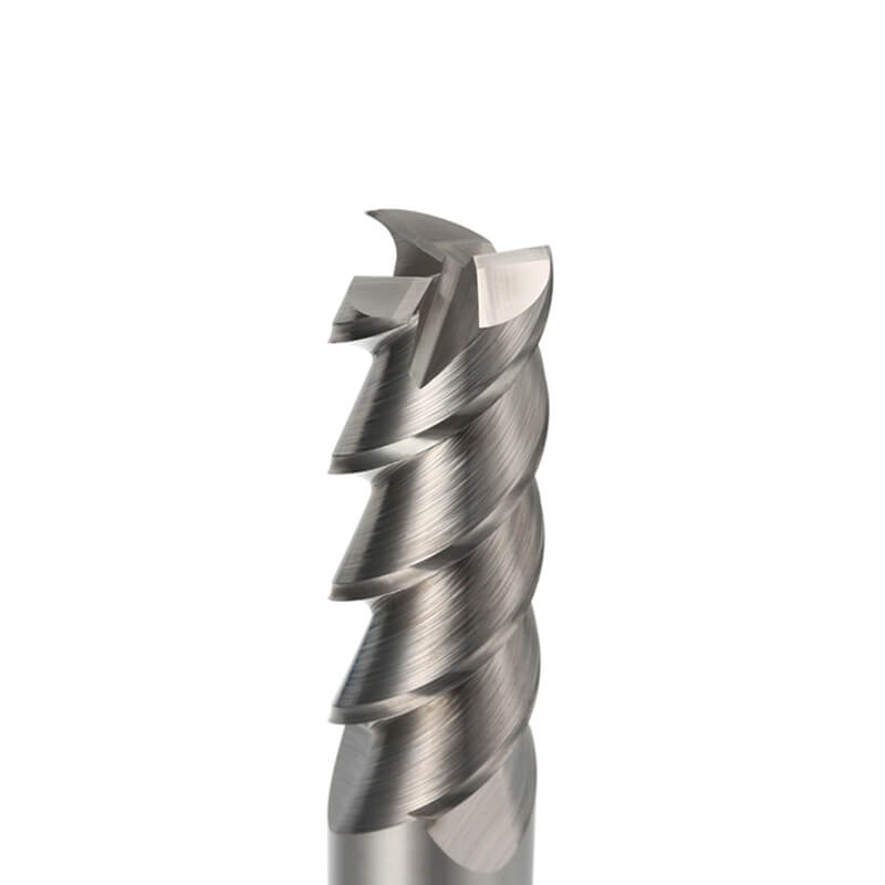
Aluminum and many copper alloys generally require sharp cutting edges, low cutting resistance, sufficient chip space, and smooth flute surfaces. Polished flutes can help reduce chip adhesion and built-up edge, particularly during slotting, cavity machining, and high-speed cutting.
Two- or three-flute tools are commonly considered where chip volume is high, although the final flute count should still match the cutter diameter, toolpath, radial engagement, and finishing requirement. Uncoated or DLC-coated tools may be selected where appropriate for the specific alloy and application.
Explore Dohre carbide end mills for aluminum machining for square, ball nose, corner radius, polished, and application-specific tool options.
Carbon Steel and Alloy Steel
Steel machining normally requires a balance of cutting-edge toughness, wear resistance, heat resistance, and chip evacuation. The correct configuration depends on material hardness, cutting engagement, machining stage, and whether the operation is continuous or interrupted.
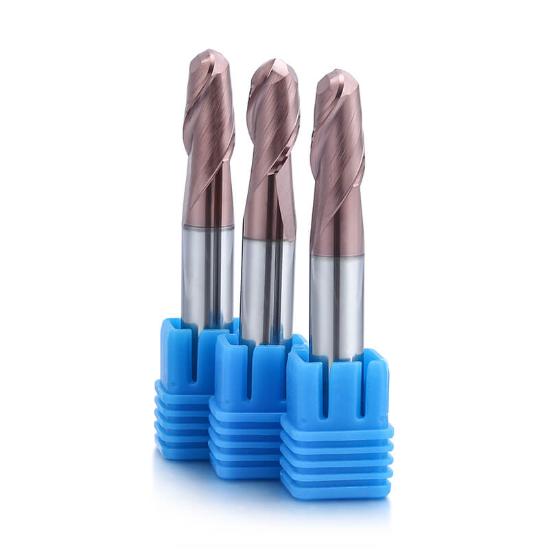
Square end mills are commonly used for flat surfaces, slots, shoulders, and side walls. Ball nose tools are used for curved profiles, while corner radius tools provide stronger corner support for shoulders, side walls, and profile machining.
Stainless Steel
Stainless steel can generate cutting heat, work hardening, chip adhesion, and vibration. The tool should provide stable edge strength, suitable positive cutting action, controlled chip formation, and reliable evacuation from the cutting zone.
Tool geometry and coating should be designed specifically for stainless steel rather than selected only by hardness. Dohre carbide end mills for stainless steel are available for different slotting, side-milling, profiling, semi-finishing, and finishing requirements.
Mold Steel
Mold steel applications may include cavity roughing, wall machining, insert production, profile semi-finishing, and surface finishing. Selection should consider the actual hardness, material condition, cavity depth, tool overhang, and required profile accuracy.
Different machining stages may require separate roughing and finishing tools. A tool optimized for material removal is not automatically the best choice for final mold-surface finishing.
Hardened Steel
Hardened steel requires a rigid machine setup, stable toolholding, controlled cutting engagement, and a cutter designed for the relevant hardness range. High-hardness carbide tools can be used for suitable applications, while CBN tools may be considered for HRC60+ hardened or quenched steel finishing under stable conditions.
Edge preparation and cutting parameters are especially important because excessive impact, runout, or unstable engagement can cause premature chipping.
Titanium Alloy
Titanium alloy machining requires careful control of cutting heat, adhesion, chip formation, and cutting stability. Excessive tool engagement or poor chip evacuation can concentrate heat around the cutting edge and accelerate wear.
Select a cutter with a suitable carbide substrate, coating, rake angle, flute space, and anti-adhesion design. The operation should also use stable engagement and a toolpath that avoids sudden cutting-force changes.
Graphite and Abrasive Materials
Graphite is highly abrasive and can rapidly wear an unsuitable cutting edge. Tool wear resistance, coating adhesion, dust evacuation, and dimensional consistency are therefore central selection factors.
Diamond-coated tools are commonly considered for graphite machining. Square, ball nose, and corner radius geometries should then be selected according to whether the feature requires flat surfaces, three-dimensional contours, or stronger corner protection.
Match the End Geometry to the Machining Feature
End geometry should be selected according to the surface that must be produced. A square, ball nose, and corner radius end mill of the same diameter are not interchangeable because they contact the workpiece differently.
| End Mill Geometry | Suitable Features | Selection Priority |
|---|
| Square End Mill | Flat bottoms, slots, pockets, straight side walls, shoulders and steps | Flat surface and clear bottom-to-wall geometry |
| Ball Nose End Mill | Curved surfaces, mold cavities, freeform profiles and 3D contours | Continuous contact on changing surface angles |
| Corner Radius End Mill | Shoulders, side walls, steps, profiles and semi-finishing | Stronger cutting corner and improved edge protection |
| Roughing End Mill | Heavy stock removal and rough machining | Chip segmentation and reduced cutting pressure |
| Long-Neck End Mill | Deep cavities, recessed surfaces and restricted areas | Additional workpiece and toolholder clearance |
| Micro-Diameter End Mill | Micro slots, small cavities, miniature shoulders and fine profiles | Access to small and precision features |
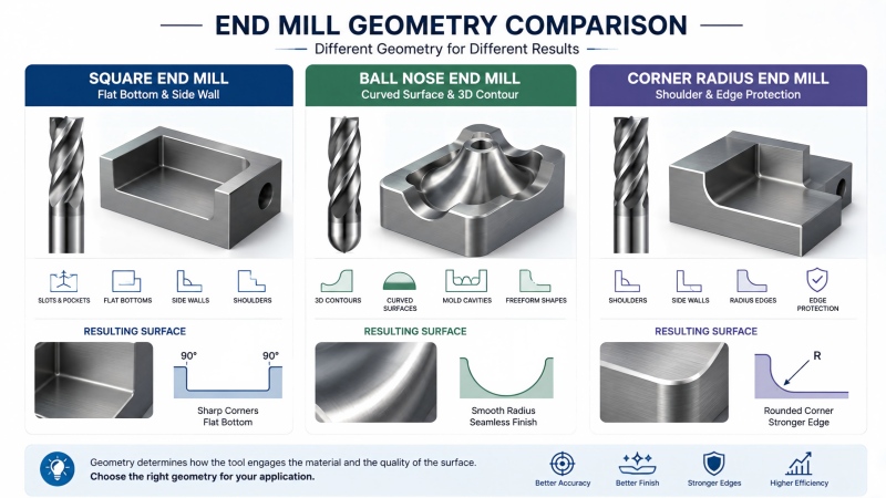
Select a square end mill when a flat bottom or straight wall is required. Select a ball nose end mill for curved and three-dimensional surfaces. Select a corner radius tool when the operation needs a mostly flat cutting area combined with stronger corner support.
Geometry selection must also consider the machining allowance. For example, a ball nose tool may be suitable for final mold contour finishing but inefficient for producing a large flat-bottom pocket.
Choose the Flute Count According to Chip Volume and Cutting Engagement
Flute count affects chip space, tool-core size, the number of cutting edges, feed capability, and surface finish. More flutes do not automatically mean better chip evacuation, and fewer flutes do not automatically mean lower productivity.
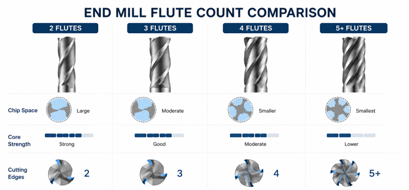
Two-Flute End Mills
Two-flute tools generally provide larger flute valleys and more chip space. They are frequently considered for aluminum, soft non-ferrous materials, deep slots, and applications where chip volume is relatively high.
Three-Flute End Mills
Three-flute designs can provide a balance between chip space and the number of cutting edges. They are commonly used in aluminum machining where both chip evacuation and increased productivity are required.
Four-Flute End Mills
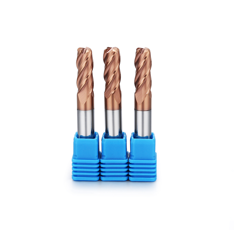
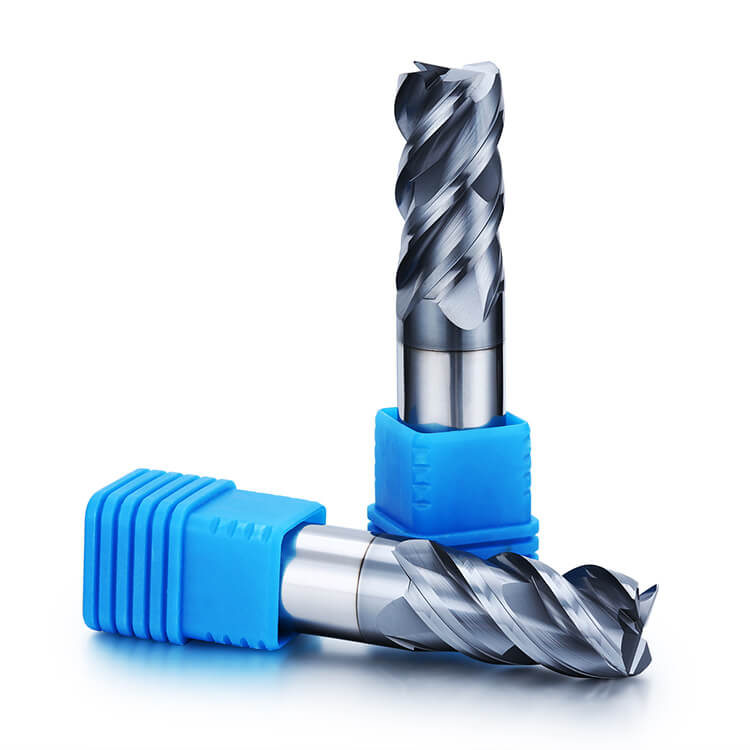
Four-flute tools are widely used for steel machining, side milling, shoulder milling, semi-finishing, and finishing. Compared with a two-flute tool of similar diameter, a four-flute design normally has a larger core and less chip space per flute.
Five or More Flutes
Higher flute counts may be useful for small radial engagement, high-efficiency toolpaths, finishing, and selected difficult-to-machine materials. They require sufficient chip evacuation and should not be selected only because more cutting edges appear more productive.
Read our detailed comparison of 2 flute vs 4 flute end mills to understand how flute count affects chip space, rigidity, feed capability, and surface finish.
Match the Tool to Roughing, Semi-Finishing or Finishing
Roughing and finishing place different demands on the cutting tool. Using one cutter for every machining stage may increase cycle time, reduce tool life, or produce inconsistent final surfaces.
| Machining Stage | Main Tool Priorities |
|---|
| Roughing | Chip evacuation, edge strength, stable material removal and resistance to impact |
| Semi-Finishing | Consistent remaining allowance, reduced vibration and stable profile preparation |
| Finishing | Profile accuracy, surface quality, dimensional consistency and controlled edge condition |
Roughing tools may use chipbreaker or serrated geometries to divide the chip and reduce cutting pressure. Finishing tools normally use a stable edge profile and smaller cutting engagement to improve surface consistency.
Leave a controlled and consistent allowance after roughing. An irregular remaining allowance can cause fluctuating cutting forces during finishing and produce uneven tool marks or dimensional variation.
Choose the Cutting Diameter, Flute Length and Tool Reach
Tool dimensions determine feature access and cutting rigidity. A cutter must reach the machining area, but unnecessary cutting length or overhang can reduce stability.
Cutting Diameter
Select the largest diameter that can safely access the required feature. A larger diameter generally provides a stronger tool body, but it may not reach narrow slots, small internal radii, or compact precision details.
Flute Length
Choose the shortest flute length that can complete the required axial cutting depth. Excess cutting length may increase deflection and reduce tool rigidity, particularly with small-diameter cutters.
Long-Neck and Extended-Reach Tools
A long-neck end mill uses a reduced-neck section to provide clearance behind a relatively compact cutting length. It is suitable for deep cavities, recessed surfaces, narrow openings, and areas where the toolholder would otherwise interfere with the workpiece.
The neck should be only as long as required for clearance. An unnecessarily long neck increases tool deflection and makes the cutter more sensitive to vibration and unstable engagement.
Micro-Diameter Tools
Micro end mills require particularly careful control of spindle runout, toolholder accuracy, tool overhang, cutting depth, and chip evacuation. Select the shortest and most rigid configuration that can reach the micro feature.
Select the Carbide Grade, Cutting Edge and Coating Together
Coating should not be selected independently from the carbide substrate and cutting-edge geometry. A coating can improve wear or heat resistance, but it cannot compensate for an unsuitable carbide grade, excessive runout, poor chip evacuation, or incorrect cutting engagement.
| Tool Direction | Typical Considerations |
|---|
| Uncoated or Polished Tools | Sharp cutting, low adhesion and smooth chip flow for suitable aluminum or non-ferrous applications |
| DLC-Coated Tools | Low-friction surface for selected aluminum and non-ferrous machining applications |
| AlTiN / TiAlN-Type Coatings | Wear and heat resistance for suitable steel and mold-steel applications |
| Diamond Coating | High wear resistance for graphite and selected abrasive non-metal materials |
| CBN Cutting Tools | Specialized finishing of HRC60+ hardened and quenched steels under stable conditions |
The final coating choice must be evaluated together with the workpiece material, hardness, cutting speed, coolant condition, edge preparation, carbide grade, and machining stage.
Check the Machine, Toolholder and Cutting Setup
A suitable end mill cannot perform consistently when the machine setup does not support it. Tool selection should therefore include the spindle, toolholder, workholding, coolant, chip evacuation, and programmed toolpath.
Machine Rigidity and Spindle Capability
Check spindle speed range, power, torque, bearing condition, and machine rigidity. Large cutters and high-engagement roughing require different machine capability from micro tools and light finishing operations.
Toolholder Runout
Excessive runout causes uneven tooth loading. One cutting edge may remove more material than the others, accelerating wear and increasing the risk of chipping, particularly with micro-diameter and long-neck tools.
Tool Overhang
Keep tool overhang as short as the feature permits. Excessive overhang reduces rigidity and may increase chatter, dimensional variation, surface marks, and tool breakage.
Chip Evacuation and Coolant
Chip packing can cause recutting, heat accumulation, scratches, built-up edge, and edge damage. Select the flute count, toolpath, air blast, coolant, or dust extraction method according to the workpiece material and cavity geometry.
Cutting Parameters
Do not select spindle speed from a material name alone. Start with cutting data for the specific cutter diameter, carbide grade, coating, flute count, workpiece material, and operation. Then adjust according to radial engagement, axial depth, tool overhang, machine condition, chip evacuation, and tool wear.
Quick End Mill Selection Table
The following table provides general selection directions rather than fixed cutting parameters. The final tool configuration should be confirmed from the actual material, drawing, machining allowance, machine setup, and production target.
| Application | Tool Geometry | Flute Direction | Main Selection Priority |
|---|
| Aluminum Slotting | Square end mill | Usually lower flute count with sufficient chip space | Sharp edge, polished flute and reduced chip adhesion |
| Steel Side Milling | Square or corner radius | Selected according to engagement and chip volume | Edge strength, wear resistance and vibration control |
| Stainless Steel Profiling | Square or corner radius | Material- and engagement-specific | Stable cutting, anti-adhesion performance and chip evacuation |
| Mold Cavity Finishing | Ball nose end mill | Selected for profile accuracy and finish | Ball-radius accuracy, runout and controlled step-over |
| Hardened Steel Finishing | Ball nose, corner radius or suitable CBN tool | Stable geometry for small cutting engagement | Hardness capability, edge strength and rigid setup |
| Graphite Contouring | Square, ball nose or corner radius | Based on feature and dust evacuation | Wear resistance and suitable diamond coating |
| Deep Cavity Machining | Long-neck square, ball nose or radius tool | Based on material and chip evacuation | Minimum necessary neck length and controlled deflection |
| Micro Features | Micro flat, ball nose or corner radius tool | Based on diameter, material and chip volume | Low runout, short overhang and stable entry |
Common End Mill Selection Mistakes
Selecting Only by Workpiece Material
Material is the starting point, but the tool must also match slotting, side milling, contouring, roughing, finishing, cavity depth, and feature geometry.
Ignoring Cutting Length and Tool Overhang
A cutter may have the correct diameter and coating but still perform poorly when the cutting length or tool overhang is unnecessarily long.
Using Insufficient Chip Space
Deep slots and high-engagement cuts generate significant chip volume. A flute configuration with insufficient chip space may cause packing, heat accumulation, recutting, and edge damage.
Using One Tool for Roughing and Finishing
Roughing and finishing have different priorities. Separating the two stages can improve allowance control, final surface consistency, and tool-life management.
Choosing Coating Without Considering the Substrate and Edge
Coating is only one part of the tool system. Carbide grade, edge preparation, rake angle, flute design, cutting engagement, and coolant conditions must also be suitable.
Ignoring Toolholder Runout
Excessive runout produces unequal tooth loading and can cause premature wear even when the end mill itself is correctly designed.
Selecting an Excessively Long Neck
Long-neck tools should provide enough clearance without adding unnecessary reach. The shortest practical neck length generally provides better rigidity.
FAQ
How do I choose the right end mill?
Start with the workpiece material and machining feature. Then determine the required end geometry, machining stage, flute count, cutting diameter, cutting length, tool reach, carbide grade, coating, and machine conditions.
Should I use a square, ball nose, or corner radius end mill?
Use a square end mill for flat bottoms, slots, straight walls, and shoulders. Use a ball nose tool for curved surfaces and three-dimensional contours. Use a corner radius tool when the application requires stronger corner protection combined with side-wall, shoulder, or profile machining.
Which end mill is best for aluminum?
Aluminum tools generally require sharp cutting edges, sufficient chip space, smooth or polished flutes, and low adhesion. The exact flute count and coating depend on the alloy, cutter diameter, operation, cutting engagement, and finishing requirement.
Which end mill is best for stainless steel?
Select a carbide end mill designed for stainless steel with stable edge strength, suitable cutting action, vibration control, chip evacuation, and a coating matched to the material and cutting conditions.
How many flutes should an end mill have?
The correct flute count depends on chip volume, material, cutter diameter, radial engagement, machining depth, toolpath, and surface requirement. Lower flute counts generally provide more chip space, while higher flute counts provide more cutting edges and often a larger tool core.
How should I choose the cutting length?
Select the shortest flute length that can complete the required axial cutting depth. Additional cutting length should only be used when the feature requires it.
When should I use a long-neck end mill?
Use a long-neck tool when a standard end mill cannot reach a deep or restricted feature without toolholder or workpiece interference. Keep the neck only as long as necessary for clearance.
Can one end mill be used for roughing and finishing?
Some tools can perform light roughing and finishing under suitable conditions, but separate tools are often more effective when roughing requires high material removal and finishing requires tight dimensional or surface-quality control.
How do I choose an end mill coating?
Select the coating together with the workpiece material, carbide substrate, cutting-edge geometry, cutting temperature, coolant condition, machining stage, and cutting parameters. Do not choose a coating only from its hardness or color.
What information is needed for a custom end mill quotation?
Provide the workpiece material and hardness, machining feature, cutter diameter, flute length, neck dimensions, shank diameter, overall length, flute count, coating preference, machining stage, required quantity, machine condition, and any available drawing or sample.
Conclusion
Selecting the correct end mill requires a complete view of the machining application. Workpiece material determines the basic substrate, coating, and edge direction, while the feature geometry determines whether a square, ball nose, corner radius, long-neck, or micro-diameter tool is required.
Flute count, cutting length, tool reach, roughing or finishing stage, machine rigidity, toolholder runout, chip evacuation, and cutting engagement must then be evaluated together. A tool that matches only one of these factors may not provide stable production performance.
Dohre manufactures standard and custom solid carbide end mills for CNC machining. Tool dimensions, carbide grade, coating, flute geometry, end profile, and application-specific designs can be developed according to customer machining requirements.
Need Help Selecting the Right End Mill?
Send us your workpiece material, machining feature, tool diameter, cutting depth, required surface finish, machine conditions, and production quantity. Dohre can recommend a suitable standard tool or develop a custom end mill for your application.
Contact Dohre