


Get In Touch
Do you have a questions or an issues we can help you with?
Let’s talk about your project and how Dohre can help get your tools designed, manufactured and ready for the market.


Reading volume: 149

Release time :2026-08-21
Estimated reading time:
Discover high-precision, AS9100-certified CNC tools engineered for aerospace machining. Protect high-value titanium and nickel alloy parts with advanced carbide end mills, zero-defect process control, and full supply chain traceability. Get a custom quote today!
The aerospace manufacturing industry operates under a zero tolerance policy for material defects and structural failure. When machining complex components like structural titanium wing spars or nickel alloy turbine disks, even a tiny dimensional drift can lead to immediate part rejection.
Raw billets often cost tens of thousands of dollars, making unexpected tool breakage an unacceptable financial risk for machine shops.Meeting strict aerospace standards requires a deep understanding of cutting mechanics, rigid quality certifications, and complete process control.
Balancing tool geometry, heat resistant coatings, and shop floor procedures allows manufacturers to protect expensive workpieces while maintaining reliable production schedules.
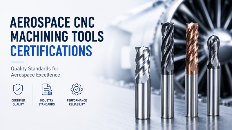
Machining materials like Titanium Ti 6Al 4V and Inconel 718 create extreme thermal and mechanical strain. These metals exhibit low thermal conductivity, which forces cutting heat to concentrate directly at the tool tip rather than transferring into the chip.
Combined with rapid work hardening tendencies, standard cutters experience severe flank wear and notch failure within minutes of engagement.
Carbon Fiber Reinforced Polymers present a completely different set of physical challenges. Because carbon fiber materials are highly abrasive and non homogeneous, conventional end mills quickly lose their sharp edge.
Dull cutting edges push composite layers apart, causing severe resin delamination, surface burrs, and fiber pull out that compromise structural integrity.
Aerospace structural components undergo rigorous non destructive testing before installation. A single micro fracture or thermal stress mark caused by a failing tool leads to immediate component rejection. Because scrap costs are exceptionally high, aerospace suppliers prioritize predictable tool wear and process stability over aggressive metal removal rates.
Having identified the severe mechanical challenges of aerospace materials, let us explore the specialized tool technologies designed to withstand these environmental conditions.
Withstanding extreme cutting temperatures requires micro grain tungsten carbide substrates with high transverse rupture strength.
Advanced Physical Vapor Deposition coatings provide a physical heat shield, lowering friction and preventing chemical diffusion between the tool and heat resistant alloys.
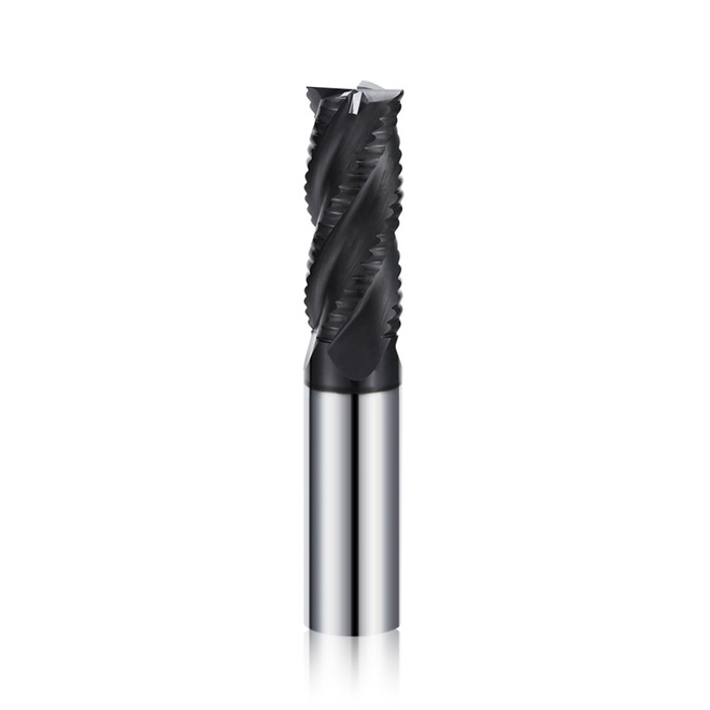
Specialized solutions like a dedicated DEX Series End mill for titanium alloy deliver the necessary toughness to resist thermal shock during heavy milling passes.
Harmonic chatter damages surface finishes and accelerates cutter breakage during deep pocket milling. Modern aerospace tooling utilizes unequal flute indexing and variable helix angles:
Asymmetric Flute Spacing: Disrupts harmonic frequencies to eliminate chatter during deep cavity cuts.
Variable Helix Angles: Smoothes the transition as each cutting edge enters and exits tough alloy surfaces.
Optimized Rake Angles: Reduces cutting resistance while maintaining a strong, supported tool edge.
Standard flood coolant often fails to reach the active shear zone in deep slots. Internal through coolant channels spray high pressure fluid directly at the cutting edge, flushing chips out instantly and preventing double cutting in deep cavities.
| Tool Design Feature | Machining Application | Performance Advantage |
|---|---|---|
| Micro Grain Substrate | Titanium and Inconel milling | Prevents micro chipping under high mechanical loads |
| Variable Flute Spacing | Deep pocket rib machining | Suppresses harmonic chatter and improves surface finish |
| High Pressure Coolant | Deep slotting and cavity milling | Flushes chips immediately and lowers shear zone heat |
With advanced tool designs established, verifying manufacturing quality through recognized industry certifications becomes the next essential requirement.
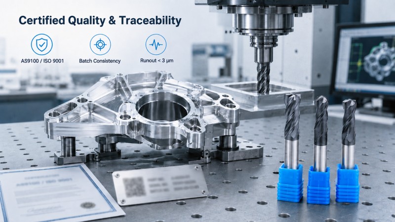
Aerospace suppliers must maintain complete operational compliance with international quality standards. Tooling suppliers support this requirement by operating under certified AS9100 and ISO 9001 frameworks.
Partnering with a dedicated manufacturer that supplies certified Milling Tools for Aerospace ensures that cutting tools pass multi stage quality inspections and use pure virgin raw materials.
Precision aerospace milling requires sub micron manufacturing tolerances across every batch. Specialized optical measuring systems verify flute symmetry, shank runout, and edge honing profiles.
Controlled edge preparation removes microscopic burrs from the ground edge, preventing initial chipping and stabilizing tool life.
Once quality certification standards are met, maintaining batch consistency across long production runs becomes critical for automated facilities.
Aerospace quality control begins long before grinding takes place. High purity carbide rods with consistent grain density ensure uniform fracture resistance. Leading manufacturers track Material Test Reports for every raw material batch, guaranteeing that structural strength remains identical across different production lots.
Automated manufacturing cells rely on pre set offset parameters during lights out shifts. If a new batch of tools shows even a five micron variation in radius or pitch, the automated cell risks dimensional drift or premature tool failure.
Sourcing from a reliable supplier of Carbide drill bits manufactured under tight process controls guarantees the repeatability needed for unmonitored production.
Complete transparency across the supply chain requires individual tool identification. Etching unique serial numbers and identification codes onto the tool shank allows shop floor management systems to track total usage, regrind history, and original rod batch data for audit compliance.
To ensure these certified tools perform reliably on the shop floor, technical operators must follow structured setup and monitoring procedures.
High speed milling of structural aluminum or thin walled wing skins requires strict dynamic balance verification. Operating at elevated spindle speeds amplifies small tool eccentricities:
1. Dynamic Balance Verification: Target: Eliminate centrifugal vibration.
Ensure complete tool and holder assemblies meet G2.5 balance standards at operational speeds up to 25,000 RPM.
2. Spindle Runout Inspection: Target: Prevent uneven tooth loading.
Verify total indicator reading runout stays below three microns at the cutting edge using a dial indicator.
3. Preset Tool Length Verification: Target: Maintain dimensional accuracy.
Measure total tool length and radius offsets using laser presetter systems before loading tools into the machine magazine.
Waiting for a tool to fail before replacing it is unacceptable when machining high value components. Establishing a predictive replacement policy based on microscopic wear measurements prevents work hardening damage and guarantees stable dimensional tolerances.
Before finalizing tool procurement plans, evaluating practical factors like pricing, lead times, and custom options helps avoid production delays.
Custom aerospace tool costs depend on raw carbide substrate grade, geometry complexity, multi layer PVD coating types, and required inspection documentation. Specialized corner radii, custom neck reach lengths, and sub micron grinding procedures increase manufacturing time.
Complete Material Test Reports and individual tool serial etching also require additional quality verification steps. For accurate pricing based on your specific component requirements, contact Dohre CNC Tools engineering team directly.
A frequent mistake is using general purpose end mills lacking polished flutes or specialized rake geometries. High speed aluminum milling using tools like an AEX Series End mill for aluminum requires mirror polished flutes to prevent material welding and chip packing.
Choosing standard tools without proper chip clearance leads to sudden tool clogging and catastrophic cutter breakage.
Service life should be evaluated by tracking dimensional consistency and flank wear progression rather than total cut time alone. Once flank wear reaches two tenths of a millimeter, cutting forces increase significantly, rising the risk of work hardening the workpiece. Setting strict life limits based on wear metrics ensures repeatable quality across production batches.
Standard catalog tools usually ship immediately from inventory, whereas custom geometries require specialized grinding programs and dedicated coating cycles.
Custom tool manufacturing typically takes two to three weeks from initial drawing approval. Establishing stable tool supply programs helps machine shops maintain continuous production without stock shortages.
Achieving consistent precision in aerospace CNC machining requires a complete engineering approach. Combining specialized carbide substrates, advanced PVD coatings, rigid quality certifications, and complete batch traceability ensures dimensional accuracy while eliminating costly scrap.
Partnering with an experienced cutting tool manufacturer allows machine shops to optimize cutting parameters and maintain reliable production. Explore full product options or consult with Dohre CNC Tools technical specialists to enhance your aerospace machining operations today.
Do you have a questions or an issues we can help you with?
Let’s talk about your project and how Dohre can help get your tools designed, manufactured and ready for the market.
By continuing to use the site you agree to our privacy policy Terms and Conditions.