


Get In Touch
Do you have a questions or an issues we can help you with?
Let’s talk about your project and how Dohre can help get your tools designed, manufactured and ready for the market.


Reading volume: 140

Release time :2026-08-22
Estimated reading time:
Learn how to prevent edge chipping in graphite electrode machining. Optimize diamond-coated tools, CAM toolpaths, and parameters. Contact Dohre today!
Graphite electrodes are central to modern electrical discharge machining in mold and die manufacturing, but edge chipping remains a costly challenge on the shop floor. When fragile corners snap during final milling passes, whole workpieces are often scrapped, wasting expensive materials and critical machining hours.
Understanding why these fractures happen and taking control of your milling process allows you to eliminate unexpected edge breakage. By choosing the right cutting tools, refining programming strategies, and optimizing machine setup, shops can achieve clean edges and repeatable precision.
Synthetic graphite differs significantly from common industrial metals. Because it lacks a ductile crystalline structure, it does not form continuous metallic curls during milling. Instead, the cutting action relies on localized micro fracturing that releases fine carbon powder. When cutting forces exceed the flexural limit of the material at an unsupported border, sudden chunking occurs.
Several practical factors accelerate this edge failure during standard CNC passes:
Corner Exit Pressure: Cutting loads spike as end mills exit ninety degree sharp turns, snapping unsupported outer walls.
Tool Edge Dullness: Worn cutting edges push material outward rather than shearing it cleanly, causing severe edge breakout.
Dust Accumulation: Packed graphite powder in tool flutes increases friction, generating micro collisions along thin feature boundaries.
Having identified the mechanical root causes of material failure, let us examine how selecting proper tooling solutions protects fragile workpiece features.
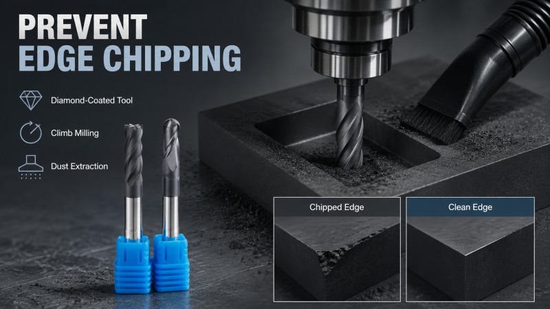
Standard carbide cutters deteriorate rapidly under the abrasive friction of graphite dust. As the cutting edge rounds off, radial forces increase sharply, leading directly to edge breakout. Applying CVD diamond films or using PCD diamond end mills provides an extremely hard shield against physical wear.
This coating retains razor sharp cutting edges across long cycles, lowering cutting resistance and preventing material push out.
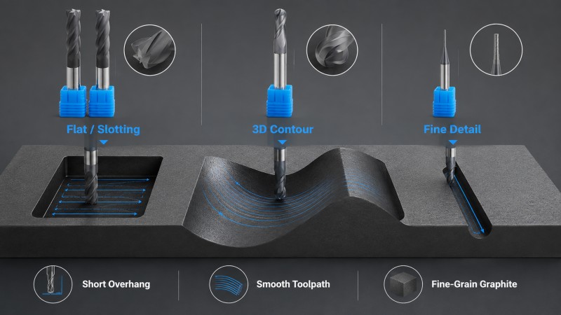
Tool geometry dictates force distribution during entry and exit moves. Selecting positive rake angles and appropriate flute counts reduces cutting pressure while maintaining structural rigidity across different geometry types:
| Tool Geometry Type | Primary Applications | Advantage for Edge Protection |
|---|---|---|
| Square End Mill | Flat surface finishing and planar slotting | Creates clean vertical shoulders without deflection |
| Ball Nose End Mill | Curved surfaces and 3D contour finishing | Evenly distributes chip load across complex contours |
| Corner Radius End Mill | Side wall finishing and shoulder milling | Strengthens the outer tool tip against premature chipping |
Tooling manufacturers engineer series like the MEX Series End Mill for graphite to combine specialized diamond coatings with ultra fine carbide substrates, ensuring smooth chip evacuation and long term edge stability.
With the right cutting tools selected, the next step involves optimizing CAM toolpaths to maintain balanced cutting forces.
Programming choices dictate the direction and magnitude of impact forces acting on delicate graphite borders. Abrupt changes in cutter engagement are a primary cause of corner fractures, making controlled tool motion essential. Always select climb milling during path generation.
This approach enters the cut at maximum thickness and exits at zero thickness, directing mechanical pressure back into the solid stock rather than lifting delicate outer margins.
Smooth motion control prevents force spikes on outer boundaries:
Arc Entry Paths: Program circular arc roll in and roll out moves to avoid perpendicular impact on sharp margins.
Trochoidal Slotting: Use dynamic trochoidal toolpaths in tight grooves to keep radial engagement constant and low.
Corner Pre Chamfering: Machine a slight chamfer around outer stock boundaries before roughing to eliminate weak sharp corners.
Beyond toolpaths and cutter selection, external physical variables also exert strong influence over edge quality.
Physical material grade, workholding rigidity, and dust extraction directly impact machining stability. Neglecting these external factors can cause edge failure even when using optimal CAM paths and specialized tools.
Synthetic graphite grades vary by grain structure. Complex, thin ribbed electrodes require fine grain or iso molded grades with particle sizes under five microns. Coarser grades feature lower flexural strength, making delicate features prone to micro fractures during detail work.
Inadequate dust removal allows abrasive powder to pack around the cutter, creating severe friction and tool binding:
High Vacuum Suction: Maintain strong dry suction directly at the cut zone to clear fine dust immediately.
Vibration Control: Keep tool overhang short, maintaining a length to diameter ratio under three to one to prevent chatter marks.
To systematically identify and resolve these operational issues, implementing a standardized troubleshooting protocol is essential.
When corner breakage occurs during production, technical operators should apply a structured process to isolate root causes quickly.
First, check spindle runout with an indicator to ensure deviation stays below five microns, and verify that clamping fixtures secure the workpiece firmly near the cutting surface without creating bending stress.
Confirm that tool overhang stays minimal, examine the cutting edge under magnification, and replace tools immediately if diamond film peeling or edge rounding is visible.
Next, verify that climb milling is active on your CAM controller. Swap straight corner exits for smooth arc moves, and reduce stepover width on delicate thin wall passes while keeping spindle speeds high.
Finally, ensure the vacuum extraction nozzle targets the exact point of cutting to eliminate powder re cutting and localized friction heat.
Before concluding your process plan, reviewing common operational questions helps prevent secondary machining issues.
Custom graphite tool pricing depends on substrate grade, flute geometry complexity, and coating thickness. High quality Chemical Vapor Deposition diamond coatings require specialized chemical reactors, which increases production costs compared to standard physical vapor coatings.
Special radii, extra long shanks, or custom necking configurations also impact tool manufacturing time. For accurate pricing based on your specific tooling requirements, contact Dohre CNC Tools engineering team directly.
Selecting a low cost, coarse grain graphite grade for intricate electrodes is a frequent mistake. Coarse graphite lacks the flexural strength needed to support thin ribs or sharp internal corners during milling. Using coarse grades for detailed electrode geometries almost always results in edge breakage regardless of cutter quality.
Monitor surface finish trends and corner retention rather than checking for visible wear marks alone. As diamond film gradually thins, cutting forces rise, causing microscopic flaking on workpiece edges. Tracking dimensional drift or listening for subtle spindle pitch changes provides early warning before full tool failure occurs.
Standard catalog cutting tools usually ship immediately, whereas custom geometries require tailored tool grinding cycles and specialized diamond coating runs.
Custom cutter manufacturing generally takes two to three weeks from final design approval. Establishing stable tool supply programs helps mold shops maintain consistent production without unexpected downtime.
Preventing edge chipping during graphite electrode machining requires a balanced engineering strategy. Combining ultra fine grain graphite with diamond coated cutters, rigid setups, and climb milling strategies ensures consistent dimensional accuracy and protects delicate workpiece details.
Partnering with an experienced cutting tool manufacturer allows shops to lower tooling costs and eliminate costly scrap. Explore solid carbide end mills or request custom tool technical support from Dohre CNC Tools to optimize your milling operations today.
Do you have a questions or an issues we can help you with?
Let’s talk about your project and how Dohre can help get your tools designed, manufactured and ready for the market.
By continuing to use the site you agree to our privacy policy Terms and Conditions.