


Master high-speed milling for HRC 60–68 hardened steel. Learn how to control radial engagement, optimize tool geometry, and troubleshoot chip issues with Dohre HEX tools.


Reading volume: 26

Release time :2026-09-17
Estimated reading time:
Master high-speed milling for HRC 60–68 hardened steel. Learn how to control radial engagement, optimize tool geometry, and troubleshoot chip issues with Dohre HEX tools.
High speed milling for hardened steel depends on keeping cutting conditions stable while controlling heat, tool load, and chip evacuation.
Small changes in engagement, tool rigidity, or cutting geometry can quickly affect edge wear and chip formation.
This guide explains the key HSM considerations for hardened steel and shows how chip behavior can help identify common cutting problems.
High speed milling of hardened steel typically uses a small radial width of cut to control cutting forces and heat. Lower radial engagement reduces edge contact with the workpiece, helping maintain stable cutting.
Radial engagement should be matched with feed per tooth, axial depth, tool diameter, workpiece hardness, and machine rigidity. Excessive engagement can increase cutting load and accelerate edge wear or chipping.
Chip thickness depends mainly on feed per tooth and radial engagement. If feed is too low, the cutting edge may rub instead of cut, increasing friction and heat.
Maintaining a suitable feed per tooth helps produce consistent chips and reduces rubbing. Feed should therefore be adjusted together with radial engagement rather than independently.
Solid carbide is widely used for high speed milling because it offers high hardness, rigidity, wear resistance, and thermal stability. These properties help maintain edge strength under the mechanical and thermal loads generated during hardened steel milling.
The relationship between carbide substrate, rigidity, heat resistance, and high speed machining is also important when selecting solid carbide end mills for high speed machining.
Cutting speed should match workpiece hardness, tool diameter, carbide grade, coating, machining stage, and tool geometry. Higher hardness does not mean simply increasing spindle speed.
The starting value should follow the tool manufacturer's recommended cutting data, then be adjusted according to actual machine and cutting conditions.
Feed per tooth determines the material removed by each cutting edge. Too little feed can increase rubbing and heat, while excessive feed can overload the edge.
For HSM, feed per tooth should be matched with radial engagement, cutter diameter, flute count, workpiece hardness, and machining operation to maintain stable chip formation.
Axial depth determines how much of the cutting edge engages the workpiece. Controlled axial engagement can help maintain stable cutting forces during hardened steel finishing and semi finishing.
Deep engagement can increase deflection and vibration, particularly with slender tools. Tool length, holder rigidity, machine condition, and cutting load should therefore be considered together.
Tool rigidity becomes increasingly important as workpiece hardness increases. A larger core diameter provides greater cross sectional support and helps reduce deflection during side milling and finishing.
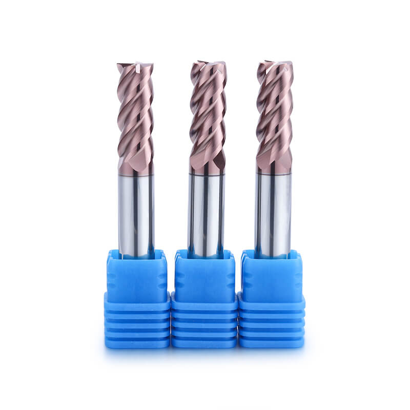
A square end mill for HRC 60 to HRC 68 hardened steel can use a reinforced core for greater stability. This geometry suits side milling, shoulder machining, and contour finishing. HEX square end mill for hardened steel is one example.
Rake angle affects both cutting resistance and edge strength. In hardened steel, an overly aggressive edge can be more vulnerable to micro chipping when cutting loads change.
A supported cutting edge can improve resistance to mechanical loading. Rake angle should be selected together with carbide grade, coating, helix geometry, and machining conditions.
Helix geometry affects cutting engagement, chip movement, and cutting stability. A suitable helix can distribute cutting action more gradually as the flute enters the workpiece.
Helix angle should be considered together with tool diameter, flute geometry, radial engagement, and workpiece hardness rather than as an isolated parameter.
Effective chip evacuation prevents chips from remaining in the cutting zone and being recut. Recutting increases friction, heat, and edge wear.
This is especially important in deep cavities and narrow features where chips can accumulate. Air blast or another suitable evacuation method can help remove chips from the cutting zone.
Sudden changes in engagement can create impact loads on the cutting edge, particularly at corners, slot exits, or abrupt changes in radial engagement.
A stable toolpath should maintain predictable cutter engagement. Smooth entries and controlled corner transitions help reduce load changes and support consistent chip formation.
Chip recutting often indicates poor chip evacuation. The risk increases in enclosed cavities, narrow slots, and toolpaths that repeatedly pass through previously cut areas.
Check chip evacuation, toolpath design, radial engagement, and cavity geometry. Improving chip removal may be more effective than simply changing spindle speed.
Powdery chips can indicate excessive rubbing or poor chip formation. Check feed per tooth, radial engagement, tool sharpness, and workpiece contact.
If feed is too low, the edge may rub instead of cut effectively. Any adjustment should remain within the recommended range for the selected tool.
Repeatedly cutting existing chips increases friction and heat. This commonly occurs in deep cavities, narrow slots, and areas with restricted chip evacuation.
Check air direction, evacuation, toolpath movement, radial engagement, and cavity geometry before changing spindle speed.
Micro chipping can result from excessive runout, tool overhang, unstable engagement, unsuitable geometry, or a mismatch between tool and workpiece hardness.
A chipped edge should not automatically be attributed to coating failure. Mechanical instability can damage the cutting edge even when the substrate and coating are suitable.
For additional troubleshooting guidance, see end mill chipping in hardened steel, which covers toolholding, cutter geometry, cutting engagement, and edge strength.
Chatter occurs when the cutting system lacks sufficient dynamic stability. Tool overhang, runout, machine rigidity, toolpath engagement, and cutting parameters can all contribute.
When chatter appears, check the mechanical setup first. Reducing overhang, improving toolholding, and controlling engagement can help restore cutting stability.
The workpiece should be evaluated according to its actual hardness rather than material name alone. H13, 718H, NAK80, and S136 can exist in different hardness conditions, and the appropriate cutter can change after heat treatment.
As hardness approaches the upper end of the machining range, edge strength, wear resistance, coating stability, and setup rigidity become increasingly important.
Roughing, semi finishing, and finishing place different demands on the cutting edge. A tool designed for stable finishing may not be the best choice for aggressive material removal.
For HRC 60 to HRC 68 hardened mold steel, tool selection should consider the machining stage together with actual hardness, part geometry, cutting engagement, and required surface quality.
Square, ball nose, and corner radius end mills serve different machining features.
Square end mills are suitable for flat surfaces, side walls, shoulders, and defined profiles. Ball nose end mills are commonly used for curved surfaces, mold cavities, and three dimensional contour finishing. Corner radius end mills can provide stronger corner support for shoulder, step, side wall, and profile finishing.
The correct cutter shape should therefore be selected according to the feature being machined rather than hardness alone.
Carbide remains a practical option for many hardened steel applications when the tool, cutting condition, and setup are properly matched. However, some high hardness finishing applications can place greater demands on wear resistance and dimensional stability.
CBN can be considered when carbide cannot maintain the required wear performance or finishing consistency under a stable machining condition. The decision should consider hardness, machining stage, required accuracy, tool life expectations, and cutting stability rather than hardness alone.
Changing from carbide to CBN should not be used to compensate for poor toolholding or unstable cutting conditions. Excessive runout, long overhang, sudden engagement, or inappropriate cutting parameters can damage any cutting tool.
Before changing tool material, the complete cutting system should be checked. Stable setup conditions provide the foundation for evaluating whether a different tool material is actually required.
Yes. High speed milling can be used for high hardness steel when the cutter, machine, toolholding, and cutting conditions are properly matched. The process should focus on controlled engagement and stable cutting rather than spindle speed alone.
There is no single parameter that determines performance. Tool rigidity, actual workpiece hardness, radial engagement, feed per tooth, cutter geometry, toolholding, and chip evacuation all influence cutting stability.
Chipping can result from excessive runout, long tool overhang, unstable engagement, unsuitable cutter geometry, excessive cutting load, or a mismatch between the cutter and workpiece hardness. These factors should be checked together.
High speed milling of hardened steel requires stable engagement, suitable tool geometry, controlled cutting parameters, and effective chip evacuation. Abnormal chip formation often indicates issues with cutting conditions, toolholding, or engagement.
For HRC 60 to HRC 68, tool selection should match the material hardness, machining stage, and part geometry. Contact Dohre for suitable end mill solutions for your application.

• Carbide: Ultra-fine grain carbide, 0.4 μm, 9% Co • Coating: Balzas DR3, heat resistance up to 1300°C • Hardness Range: HRC 60–68 • Core Diameter: Up to 68% for high rigidity • Helix Angle: 45° • Negative Rake Angle: 0° to -5° • Application: High-efficiency side milling & finishing
Learn More>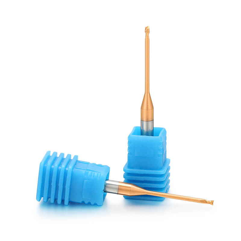
stainless steel,under hrc55. For semi-finishing&roughing(±5 μm).
Learn More>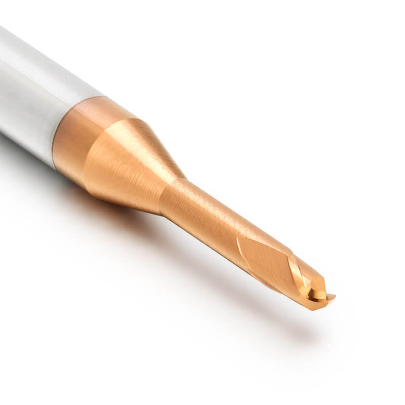
stainless steel,under hrc55. For semi-finishing&roughing(±5 μm).
Learn More>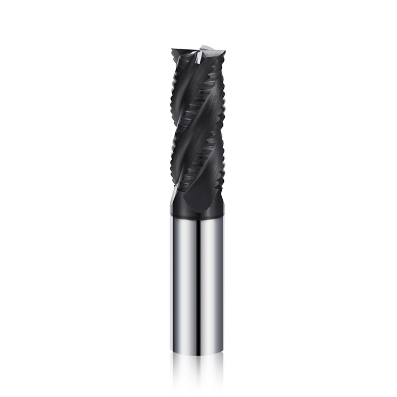
• High efficiency rough machining • Excellent chip evacuation • Strong cutting edge design • Suitable for steel, stainless steel and aluminum • Optional color coating available • Custom roughing end mills supported
Learn More>By continuing to use the site you agree to our privacy policy Terms and Conditions.