How to Choose a Micro End Mill: Diameter, Flute Length, Neck Length, and Runout
Introduction
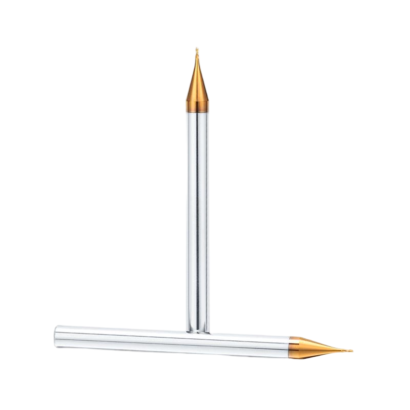
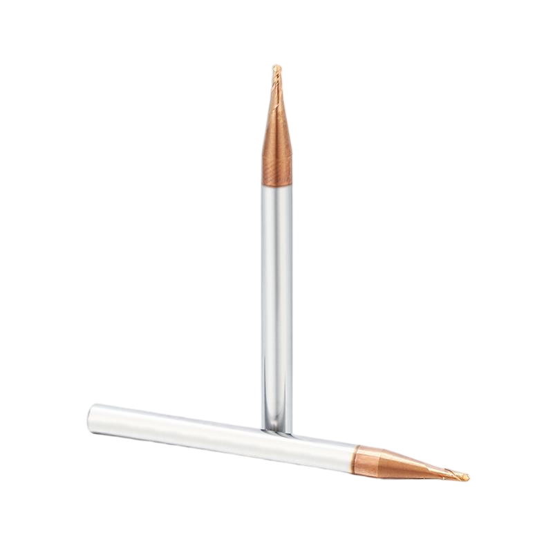
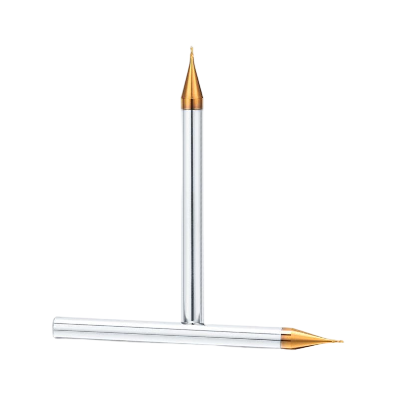
Micro end mills are used for narrow slots, miniature cavities, fine contours, small internal radii, and other restricted CNC features. Choosing the correct tool requires more than matching the cutter diameter to the drawing. Flute length, neck clearance, holder overhang, runout, chip evacuation, and workpiece material must also be considered together.
Micro end mills are commonly used for narrow slots, small cavities, fine contours, miniature shoulders, alignment features, connector openings, precision molds, electrodes, optical components, electronic housings, and other restricted CNC structures.
Although cutter diameter is usually the first dimension customers consider, it is only one part of the selection process. A tool with the correct diameter can still produce unstable results when its flute length is excessive, its neck does not provide enough clearance, its holder overhang is too long, or its runout is too large relative to the cutter size.
A reliable selection process should match the complete tool structure to the workpiece material, feature width, machining depth, internal radius, surrounding clearance, tolerance, and required surface quality.
What Is a Micro End Mill?
“Micro end mill” is a practical manufacturing term rather than one universal diameter standard. Different manufacturers and industries may use different diameter ranges when describing micro or small-diameter cutters.
From a machining perspective, a cutter should be treated as a micro end mill when its small diameter makes the process highly sensitive to runout, tool deflection, chip congestion, spindle condition, toolholding accuracy, and cutting-edge damage.
As the diameter decreases:
• The tool core becomes smaller.
• Resistance to bending decreases.
• Available chip space becomes more limited.
• Runout becomes larger relative to the cutter diameter.
• Small changes in cutting load have a greater effect on tool life.
• Edge wear and micro-chipping become more difficult to observe.
This is why a micro end mill should not be selected simply as a smaller version of a standard cutter.
Four Dimensions That Control Micro End Mill Performance
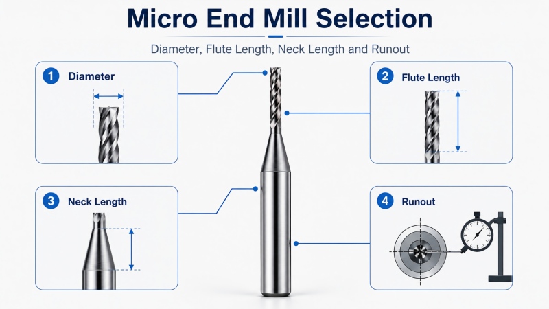
The four most important factors are cutter diameter, flute length, neck length, and actual tool overhang. Runout must then be controlled so that the cutting edges can use those dimensions correctly.
| Selection Factor | Main Function | Common Selection Mistake |
|---|
| Cutter diameter | Determines feature access, slot width, internal radius, rigidity, and chip space | Selecting a smaller diameter than the feature requires |
| Flute length | Defines the axial section that can actively cut material | Using a long-flute cutter for a shallow feature |
| Neck length | Provides clearance for deeper walls and restricted features | Using a neck longer or thinner than necessary |
| Tool overhang | Represents the unsupported length extending from the holder | Clamping the tool with excessive extension |
| Runout | Controls how evenly the cutting edges share the load | Checking only the shank instead of measuring near the cutting edge |
How to Select the Micro End Mill Diameter
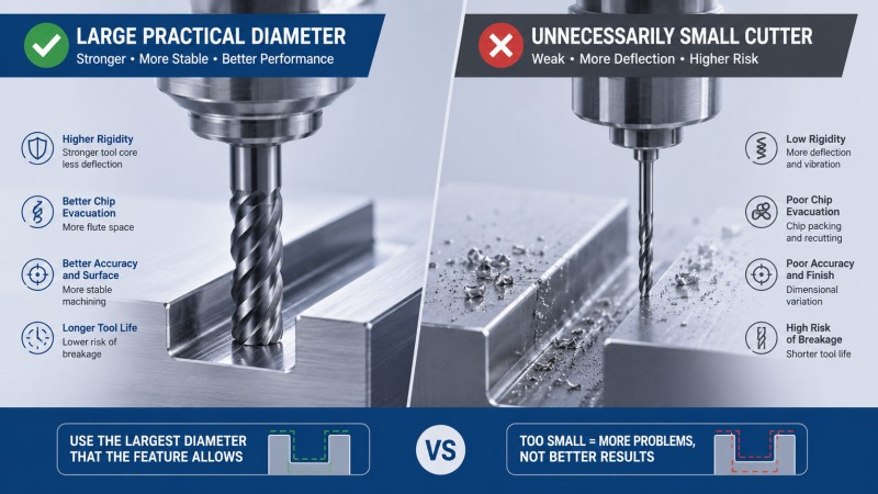
The cutter diameter must fit the required slot, cavity, internal corner, or profile. However, choosing the smallest cutter that can enter the feature is usually not the best approach.
Use the largest practical diameter that can produce the required geometry. A larger micro end mill generally provides:
• A stronger tool core.
• Greater resistance to deflection.
• More stable cutting-edge support.
• More available space for chip evacuation.
• Lower sensitivity to a given amount of runout.
Diameter Selection for Narrow Slots
When the cutter diameter is the same as the final slot width, the tool machines both slot walls at the same time. This can be efficient, but the resulting width becomes highly sensitive to cutter size, runout, deflection, wear, and spindle movement.
For a critical slot, a slightly smaller tool may be used to create the opening and finish each wall separately when the feature permits. This provides greater control over the final width, but it also requires a stable toolpath and enough space for radial finishing passes.
Diameter Selection for Small Internal Corners
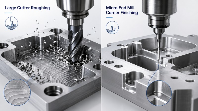
Do not use the smallest cutter to machine the complete cavity when the small diameter is required only for one or two internal corners.
A more stable process is to rough the main cavity with a larger end mill and use the micro cutter only for the remaining corner material. This reduces machining time, chip volume, tool wear, and the risk of micro-tool breakage.
| Feature | Diameter Selection Principle |
|---|
| Narrow straight slot | Select the largest diameter compatible with the required slot width and finishing strategy |
| Small internal radius | Choose a tool that can generate the specified radius without being smaller than necessary |
| Main pocket with small corners | Use a larger cutter for bulk removal and a micro end mill for corner finishing |
| Thin-wall feature | Balance tool rigidity with radial cutting force and available clearance |
| Deep restricted cavity | Consider both diameter and neck clearance rather than reducing diameter alone |
How to Select the Flute Length
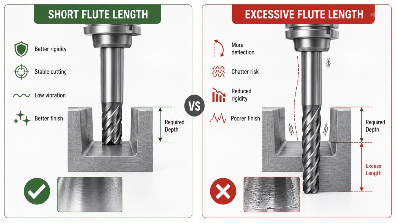
Flute length is the axial length of the cutting portion. It should be long enough to cover the material that must be machined, but it should not be substantially longer than the actual cutting depth without a clear reason.
A longer flute removes carbide from the tool core and increases the flexible cutting section. For a micro end mill, this may lead to:
• Greater tool deflection.
• Sidewall taper or dimensional error.
• Vibration marks.
• Higher sensitivity to interrupted cutting.
• Reduced resistance to sudden overload.
Use Only the Cutting Length Required by the Feature
For a shallow slot, choose a short-flute micro end mill whenever possible. A long-flute cutter does not provide an advantage when only the first part of the cutting edge is used.
For a deeper slot or cavity, the flute length must cover the intended axial engagement. However, deep machining does not always require a full-flute tool extending through the complete feature depth. A reduced-neck design may provide the required clearance while keeping the cutting portion shorter and more rigid.
| Flute Length Condition | Likely Result |
|---|
| Too short | The non-cutting section may rub against the workpiece or prevent the required depth from being reached |
| Matched to the feature | Better balance between access, rigidity, and chip evacuation |
| Much longer than required | Higher deflection, vibration, and risk of breakage without a machining benefit |
How Neck Length Differs from Flute Length
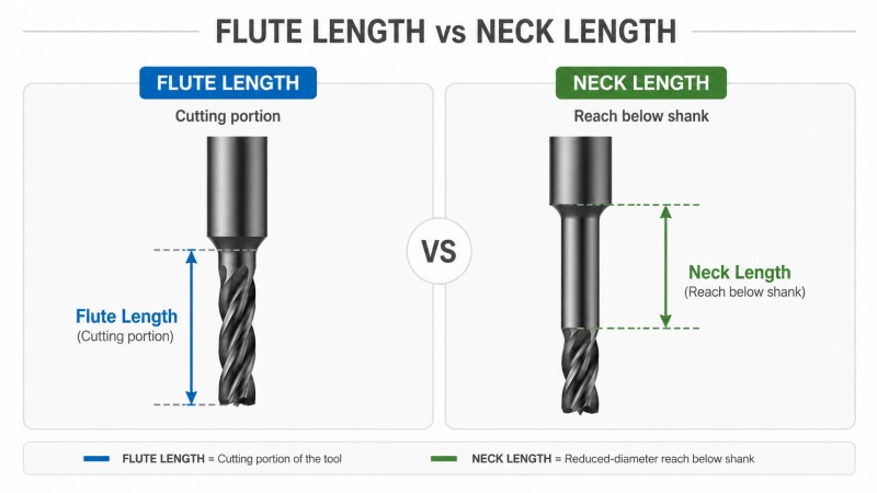
Flute length and neck length are often confused, but they perform different functions.
A reduced-neck micro end mill can reach a deeper feature without using a long cutting edge along the complete depth. This structure is useful when the cutter must pass beside a wall, shoulder, rib, or cavity opening without the larger shank contacting the workpiece.
When Is a Long-Neck Micro End Mill Useful?
A long-neck tool may be required for:
• Deep narrow cavities.
• Small features located below a surrounding wall.
• Restricted mold details.
• Deep connector openings.
• Small slots behind a shoulder.
• Fine finishing areas with limited holder clearance.
However, the neck should be only as long as necessary. Increasing neck length increases the flexible section of the tool and may reduce resistance to bending and vibration.
Long Neck Does Not Mean Long Flute
For a deep feature that requires only light finishing near the bottom, a short flute with a longer reduced neck may be more stable than a full-flute cutter of the same reach.
The correct choice depends on how much of the sidewall must actually be cut. If the entire deep wall requires axial cutting, a longer flute may be necessary. If only the bottom region or a small profile requires cutting, a short flute with neck clearance may provide a stronger solution.
Why Actual Tool Overhang Matters
Tool overhang is the unsupported distance from the holder to the cutting tip. It is not determined only by the catalog dimensions of the end mill. The way the tool is clamped in the holder also changes the actual overhang used on the machine.
A suitable micro end mill can still perform poorly when it is extended unnecessarily far from the holder.
| Overhang Condition | Effect on Machining |
|---|
| Short practical overhang | Higher rigidity, lower deflection, and more stable cutting |
| Moderate required overhang | May require lower engagement and closer monitoring of deflection |
| Excessive overhang | Greater vibration, dimensional error, poor surface finish, and breakage risk |
Clamp the tool as deeply as the feature and holder geometry allow. Do not expose additional shank or neck length simply because the end mill is manufactured with a long reach.
Why Runout Is Critical in Micro Milling
Runout is the radial deviation of the rotating cutting edge from the intended spindle centerline. In a standard-diameter cutter, a small amount of runout may still be undesirable. In a micro end mill, the same amount can represent a much larger percentage of the cutter diameter and intended chip load.
When runout is present, the cutting edges do not share the material equally. One flute may remove most of the chip while another flute cuts very little or rubs against the surface.
Possible results include:
• Rapid wear on one cutting edge.
• Unequal chip formation.
• Oversized slots.
• Poor or uneven sidewall finish.
• Burrs concentrated on one edge.
• Unstable cutting sound or vibration.
• Premature micro-tool breakage.
Measure Runout Near the Cutting Edge
Checking only the shank may not reveal the complete cutting condition. Runout should be evaluated as close to the cutting edge as the measurement method permits because holder error, collet condition, shank contamination, tool straightness, and clamping can affect the final rotating position of the cutter.
Inspect the Complete Toolholding System
Before adjusting cutting parameters, inspect:
• The spindle interface.
• The tool holder and collet.
• The cleanliness of all contact surfaces.
• The tool shank condition.
• The clamping position and insertion depth.
• The holder balance at the intended spindle speed.
• The actual runout close to the cutting edge.
The acceptable runout depends on cutter diameter, chip load, feature tolerance, and required tool life. It is more useful to control runout relative to the micro-tool size and machining requirement than to apply one universal value to every cutter.
Match the Micro End Mill to the Workpiece Material
After determining diameter, flute length, neck length, and overhang, the cutting geometry must be matched to the workpiece material. A micro end mill designed for aluminum should not automatically be used for stainless steel or hardened mold steel.
| Material | Common Micro-Milling Problem | Tool Priority |
|---|
| Aluminum alloy | Chip adhesion, built-up edge, burrs, and flute blockage | Sharp cutting edge, smooth flute, low cutting resistance, and sufficient chip space |
| Copper alloy | Smearing, ductile burrs, and surface scratching | Sharp edge, low friction, smooth chip flow, and low runout |
| Stainless steel | Cutting heat, work hardening, vibration, and edge wear | Stable edge support, wear-resistant coating, and consistent chip formation |
| Mold steel | Higher cutting resistance, corner wear, and tool deflection | Substrate, coating, rake geometry, and edge strength matched to hardness |
| Hardened steel | Rapid wear, edge chipping, heat, and vibration | High-rigidity tool structure, suitable coating, short overhang, and controlled engagement |
Dohre provides material-specific carbide end mills for aluminum, stainless steel, mold steel, hardened steel, titanium, graphite, and other CNC applications. The cutter geometry and coating should be confirmed according to the actual material rather than diameter alone.
How Flute Count Affects Micro End Mill Selection
Flute count affects chip space, tool core, cutting-edge engagement, and the number of cutting edges passing through the material.
| Flute Count | Typical Advantage | Selection Consideration |
|---|
| 2 flutes | More flute space for chip evacuation | Often considered for non-ferrous materials and narrow full-width slots |
| 3 flutes | Balance between chip space, tool core, and cutting-edge count | May suit selected aluminum profiling and finishing operations |
| 4 flutes | More cutting edges and stronger core in suitable designs | May suit steel side milling and controlled radial engagement |
Do not select flute count separately from material, slot engagement, chip size, spindle speed, cutting depth, and evacuation method. Adding more flutes reduces the space available between them, which can become a problem in a narrow micro slot.
Chip Evacuation in Small Slots and Cavities
Micro features provide very little space for chips to leave the cutting zone. Once chips become trapped, they may be cut again, pressed against the tool, or dragged across the finished surface.
Poor evacuation can cause:
Select sufficient flute space, direct air or coolant toward the cutting area, and avoid using an axial engagement that prevents chips from leaving the slot. Chips should be cleared before a precision finishing pass begins.
Do Not Select a Micro End Mill by Overall Length Alone
Overall length is useful for confirming whether the tool can be installed in the machine and holder, but it does not directly show how much working reach is available.
Two tools with the same overall length may have very different:
Always review the complete dimensional drawing rather than selecting the tool from diameter and overall length only.
Common Micro End Mill Selection Mistakes
| Mistake | Possible Result | Better Approach |
|---|
| Choosing the smallest available diameter | Low rigidity, limited chip space, and shorter tool life | Use the largest diameter allowed by the feature |
| Using a long flute for a shallow slot | Unnecessary deflection and vibration | Match flute length to the actual cutting depth |
| Using a full-flute tool for deep clearance | Weaker cutting section and unstable sidewall machining | Consider a short flute with a reduced neck |
| Selecting an excessively long neck | Higher bending and breakage risk | Use only the neck length required for clearance |
| Extending the tool too far from the holder | Poor accuracy, chatter, and shorter tool life | Keep actual overhang as short as practical |
| Ignoring runout | Unequal flute loading and premature failure | Measure the complete toolholding system near the cutting edge |
| Selecting by diameter without considering material | Adhesion, rapid wear, poor chip flow, or edge chipping | Match geometry and coating to the workpiece material |
Practical Micro End Mill Selection Workflow
1. Confirm the workpiece material. Identify the alloy, hardness, and supplied condition.
2. Identify the smallest feature. Confirm the slot width, corner radius, cavity opening, and profile dimensions.
3. Select the largest practical cutter diameter. Do not reduce diameter without a geometric reason.
4. Confirm the actual cutting depth. Select only the flute length needed to machine that section.
5. Check surrounding clearance. Determine whether a reduced neck is required.
6. Limit the neck length. Use the shortest neck that reaches the feature without interference.
7. Set the holder position. Keep actual tool overhang as short as the application permits.
8. Select flute count and geometry. Match chip space, core strength, and edge design to the material and operation.
9. Plan chip evacuation. Confirm that chips can leave the slot or cavity.
10. Measure runout. Check close to the cutting edge after the tool is clamped.
11. Use a stable machining sequence. Rough with a larger cutter where possible and reserve the micro tool for restricted areas.
12. Inspect the first machined features. Check width, wall position, burrs, surface quality, and tool condition.
Troubleshooting Micro End Mill Problems
| Observed Problem | Possible Selection Cause | What to Review |
|---|
| Micro end mill breaks during entry | Excessive overhang, unsuitable entry method, or sudden engagement | Tool reach, ramping method, axial depth, runout, and spindle acceleration |
| Slot is wider than expected | Runout, cutter deflection, diameter variation, or unstable holder | Effective cutting diameter, holder condition, runout, and finishing strategy |
| Wall is tapered | Long flute, long neck, excessive overhang, or high radial load | Tool structure, cutting direction, axial depth, and finishing allowance |
| Chips pack inside the slot | Insufficient flute space or excessive cutting depth | Flute count, chip load, axial engagement, coolant, and air direction |
| One edge wears faster | Runout or uneven cutting-edge loading | Holder cleanliness, collet condition, shank clamping, and runout near the edge |
| Poor finish in a deep feature | Excessive neck length, overhang, vibration, or chip recutting | Tool reach, radial engagement, finishing stock, and chip evacuation |
When Is a Custom Micro End Mill Useful?
Standard micro end mills can machine many small features, but catalog dimensions do not always match the required combination of diameter, flute length, neck length, neck diameter, corner radius, and holder clearance.
A custom micro end mill may be considered when the component contains:
• A non-standard slot width.
• A special cutting diameter.
• A short flute combined with an extended reduced neck.
• A restricted neck-clearance requirement.
• A special corner radius.
• A stepped or combined profile.
• A material requiring application-specific flute geometry or coating.
• A production process where standard tools require excessive overhang.
Dohre provides custom and non-standard end mills according to the workpiece material, feature drawing, cutting diameter, flute length, neck length, neck diameter, corner form, tolerance, and machine conditions.
FAQ
How do I choose the diameter of a micro end mill?
Choose the largest cutter diameter that can produce the required slot width, internal radius, or profile. Avoid selecting a smaller diameter than the geometry requires because rigidity and chip space decrease as the tool becomes smaller.
How long should the flute length be?
The flute length should cover the material that must actually be cut. A flute that is much longer than the feature depth may reduce rigidity and increase deflection without providing a machining advantage.
What is the difference between flute length and neck length?
Flute length is the active cutting section. Neck length is the relieved section behind the cutting edge that provides clearance for deeper or restricted features.
Is a long-neck micro end mill more likely to break?
A longer neck increases the flexible section of the tool and may increase deflection and breakage risk. Use only the neck length required to reach the feature and reduce cutting engagement when rigidity is limited.
Why is runout more important for a micro end mill?
The same runout represents a larger proportion of a small cutter diameter and intended chip load. It can cause one flute to carry most of the cutting force, leading to rapid wear, oversized features, and premature breakage.
Where should micro end mill runout be measured?
Runout should be checked as close to the cutting edge as the measurement method permits. Measuring only the shank may not show the final cutting condition after the tool is clamped in the holder.
Should I use a long-flute or long-neck end mill for a deep feature?
Use a long flute when the complete deep wall must be actively cut. Use a short flute with a reduced neck when only a limited cutting area requires machining but additional clearance is needed to reach it.
Why does a micro end mill produce an oversized slot?
Possible causes include runout, tool deflection, excessive overhang, cutter wear, unstable toolholding, and using a full-width cutting strategy without a separate finishing allowance.
When should a custom micro end mill be used?
A custom tool may be useful when the application requires a special diameter, short flute, extended neck, specific neck clearance, unusual corner radius, combined profile, or material-specific geometry that is unavailable in a standard catalog tool.
Conclusion
Choosing a micro end mill requires more than matching the nominal diameter to the smallest feature. Diameter controls access and rigidity, flute length defines the active cutting section, neck length provides clearance, and actual overhang determines how much unsupported tool extends from the holder.
Runout must also be controlled because unequal cutting-edge loading has a much greater effect as the cutter becomes smaller. A micro tool with the correct dimensions may still fail when it is installed with excessive runout, unnecessary overhang, or an unsuitable holder.
The most stable approach is to use the largest practical cutter diameter, the shortest suitable flute and neck length, the minimum required holder overhang, material-specific cutting geometry, and a toolholding system with controlled runout.
Dohre provides solid carbide micro-diameter end mills and custom tooling solutions for narrow slots, small cavities, fine contours, deep restricted features, optical components, electronic parts, precision molds, and other micro-milling applications. Contact us with your workpiece material, feature drawing, cutter diameter, machining depth, neck-clearance requirement, tolerance, and machine conditions for tool recommendations.