Why Do Micro End Mills Break? 10 Common Causes and Solutions
Introduction
Micro end mills can break because of runout, excessive tool reach, chip congestion, unstable entry, incorrect cutting load, or a cutter that does not match the workpiece material. This guide explains how to identify the actual cause of micro-tool failure and improve machining stability without simply reducing every cutting parameter.
Micro end mills are used for narrow slots, miniature cavities, small internal radii, fine contours, connector openings, precision molds, electronic components, optical parts, and other restricted CNC features. Their small cutting diameter provides access to these structures, but it also makes the tool more sensitive to runout, deflection, chip congestion, and sudden changes in cutting load.
When a micro end mill breaks, reducing the feed rate is often the first response. However, tool failure may continue when the actual cause is excessive overhang, an unsuitable flute length, poor chip evacuation, unstable tool entry, material adhesion, or unequal cutting-edge loading.
Effective troubleshooting starts by identifying when and where the cutter fails. A tool that breaks during entry requires a different investigation from one that fails after several parts or only breaks at the bottom of a deep slot.
Before troubleshooting breakage, it is also important to confirm that the cutter dimensions match the feature. Our guide on how to choose a micro end mill explains the relationship between cutter diameter, flute length, neck length, overhang, and runout.
Why Micro End Mills Are More Sensitive to Failure
As cutter diameter decreases, the tool core becomes smaller and its resistance to bending is reduced. At the same time, the flute has less space to carry chips away from the cutting zone.
A small amount of runout, chip packing, or tool deflection may represent a significant part of the intended cutting condition. The micro end mill may continue rotating normally until one flute suddenly receives more load than the cutting edge or tool core can support.
The failure may appear sudden, but it is often the result of several factors acting together:
•The cutter diameter is smaller than necessary.
•The flute or neck is longer than the feature requires.
•The tool extends too far from the holder.
•One flute carries more load because of runout.
•Chips remain inside the slot and are cut again.
•The tool enters the material with sudden full engagement.
•The cutting geometry does not match the material.
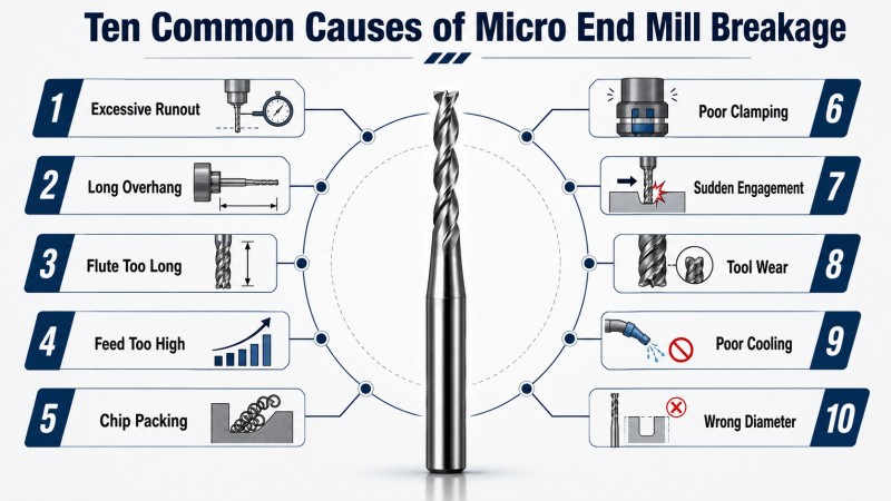
Ten Common Causes of Micro End Mill Breakage
| Cause | Typical Result | First Action |
|---|
| Excessive runout | One flute becomes overloaded | Measure runout near the cutting edge |
| Excessive tool overhang | Deflection, vibration, and sudden failure | Clamp the tool deeper where clearance allows |
| Flute or neck too long | Reduced rigidity and wall error | Match the working length to the feature |
| Cutter diameter too small | Weak core and limited chip space | Use the largest diameter permitted by the geometry |
| Unstable tool entry | Breakage during plunging, ramping, or corner entry | Review the entry method and initial engagement |
| Chip packing | Unexpected overload inside a narrow slot | Improve flute space and chip evacuation |
| Incorrect cutting load | Overload or rubbing instead of stable chip formation | Review chip load, engagement, and spindle condition together |
| Wrong geometry for the material | Adhesion, heat, edge chipping, or rapid wear | Select material-specific geometry and coating |
| Continued use after wear | Increasing force followed by sudden breakage | Establish a tool-life and inspection standard |
| Unstable machine or workholding | Vibration and inconsistent feature position | Inspect the spindle, holder, fixture, and workpiece support |
1. Excessive Runout Overloads One Cutting Edge
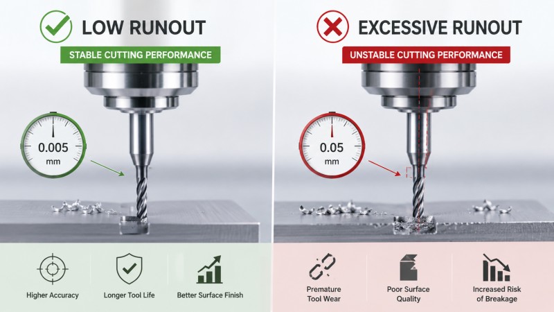
Runout causes the cutting edges to rotate at different effective radii. One flute may remove most of the material while another flute cuts very little or rubs against the surface.
This unequal loading can produce rapid wear on one cutting edge, inconsistent chip thickness, an oversized slot, poor sidewall finish, and premature breakage.
The same runout becomes more serious as the cutter diameter and intended chip load decrease. A value that appears small on a standard end mill may still be significant for a micro tool.
How to Check Runout
•Clean the holder, collet, shank, and spindle interface.
•Check for damage or wear on the collet and holder.
•Clamp the tool at the intended insertion depth.
•Measure as close to the cutting edge as the method permits.
•Rotate and reclamp the tool to identify holder-related variation.
•Recheck runout after a collision or unexpected tool failure.
2. Excessive Overhang Reduces Tool Rigidity
Tool overhang is the unsupported distance from the holder to the cutting tip. Increasing this distance makes the cutter more sensitive to radial force, vibration, and sudden engagement.
A long tool does not need to be clamped at its maximum extension. The actual overhang should be only long enough to reach the feature without causing holder interference.
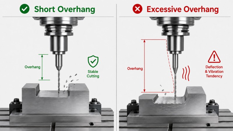
Symptoms of excessive overhang include:
•Visible vibration marks on the cavity wall.
•A tapered or oversized feature.
•Unstable cutting sound.
•Frequent failure at the same toolpath position.
•Shorter tool life even after reducing feed.
Before lowering every cutting parameter, reduce the actual overhang and confirm that the holder can approach the workpiece safely.
3. The Flute or Neck Length Is Longer Than Necessary
Flute length and neck length provide different functions. The flute is the active cutting section, while the reduced neck provides clearance behind the cutting edge.
A shallow slot does not require a long-flute tool. An unnecessarily long flute reduces the rigidity of the cutting section without improving access.
A long neck may be needed for a deep restricted feature, but it should not be longer than the actual clearance requirement. An extended neck increases the flexible part of the tool and reduces its resistance to sudden changes in cutting force.
| Feature Requirement | More Suitable Structure |
|---|
| Shallow open slot | Short flute and short overhang |
| Deep wall requiring full axial cutting | Flute length matched to the required cutting depth |
| Small feature below a surrounding wall | Short flute with the shortest practical reduced neck |
| Deep finishing near the cavity bottom | Reduced-neck finishing tool with controlled engagement |
4. The Cutter Diameter Is Smaller Than the Feature Requires
A smaller cutter is not automatically more precise. Reducing diameter also reduces core strength and available chip space.
Use the largest cutter diameter that can produce the required slot width, profile, or internal radius. When a small radius exists only in selected corners, rough the main cavity with a larger tool and reserve the micro end mill for the remaining corner material.
This strategy reduces:
•The volume of material removed by the micro tool.
•The time the cutter remains in continuous engagement.
•Chip congestion inside the cavity.
•Deflection and breakage risk.
5. Unstable Tool Entry Creates a Sudden Load
Micro end mills are particularly sensitive to sudden engagement. Direct plunging, an aggressive ramp, or entering an internal corner at full radial engagement can overload the cutting edge before stable chip formation begins.
The most suitable entry method depends on whether the cutter is center cutting, the workpiece material, available space, flute geometry, and programmed engagement.
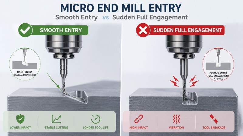
Review the entry when the cutter breaks:
•Immediately after contacting the workpiece.
•At the end of a ramp.
•When entering an existing narrow slot.
•When changing from partial to full-width engagement.
•At a sharp internal toolpath corner.
A smooth entry with controlled engagement is generally more stable than an abrupt load change.
6. Chips Become Trapped Inside the Slot
A micro slot provides limited space for the cutter and chips. If chips cannot leave the cutting area, they may be pressed against the flute, cut again, or dragged between the tool and workpiece.
Chip packing can increase cutting force suddenly, even when the programmed speed and feed have not changed.
Signs of Poor Chip Evacuation
•Chips remain packed inside the slot.
•The finished wall contains random scratches.
•Material adheres to the flute.
•Tool life changes significantly between similar parts.
•The cutter fails deeper in the feature rather than at entry.
How to Improve Chip Evacuation
•Use a flute count and flute form suited to the material.
•Avoid excessive axial engagement in a full-width slot.
•Direct air or coolant toward the cutting zone.
•Clear chips between progressive-depth passes.
•Remove roughing chips before the finishing pass.
•Inspect the tool for aluminum or copper adhesion.
7. The Cutting Load Is Too High or Too Low
An excessive chip load or cutting engagement can overload the cutter directly. However, reducing the feed too far can also create problems.
When the cutting edge removes too little material, it may rub or push the surface instead of forming a stable chip. Rubbing increases heat and wear, causing the edge to become less sharp and the cutting force to rise over time.
Cutting data should be reviewed together with:
•Actual cutter diameter.
•Flute count.
•Tool runout.
•Axial and radial engagement.
•Workpiece material.
•Tool overhang.
•Spindle speed stability.
•Chip evacuation conditions.
Do not change spindle speed or feed independently without considering how the adjustment changes chip formation and tool loading.
8. The Tool Geometry Does Not Match the Material
A micro end mill should be selected according to both the feature and the workpiece material. A cutter designed for aluminum may not have the edge support or coating required for stainless steel or mold steel.
| Material | Possible Breakage-Related Problem | Tool Priority |
|---|
| Aluminum | Built-up edge and flute blockage | Sharp edge, smooth flute, low cutting resistance, and chip space |
| Copper | Smearing, adhesion, and ductile chips | Sharp edge, low friction, and controlled chip movement |
| Stainless steel | Heat, work hardening, and edge wear | Stable edge support, suitable coating, and consistent engagement |
| Mold steel | High cutting resistance and corner damage | Substrate, edge strength, coating, and geometry matched to hardness |
| Hardened steel | Rapid wear, chipping, heat, and vibration | Rigid structure, short overhang, suitable coating, and controlled engagement |
A solid carbide micro-diameter end mill should be selected according to the actual material, feature dimensions, reach, tolerance, and machining method rather than cutter diameter alone.
9. The Tool Is Used Beyond Its Stable Wear Limit
Micro end mills may continue producing a recognizable feature after the cutting edge has begun to wear. However, increasing wear changes the effective edge shape and raises cutting resistance.
Waiting for complete tool failure can produce:
•Sudden cutter breakage inside a finished component.
•Increasing burr height.
•Changing slot width.
•Rougher sidewalls.
•Material adhesion to the flute.
•More unstable cutting from part to part.
The replacement standard should be based on the first critical feature that becomes unacceptable, not only on the number of parts completed or whether the cutter remains unbroken.
10. The Spindle, Holder, Fixture, or Workpiece Is Unstable
A high-quality cutter cannot compensate for an unstable machining system. Spindle condition, holder balance, collet wear, fixture rigidity, workpiece support, and machine movement all affect micro-tool loading.
Check the complete system when breakage continues after replacing the tool:
•Spindle runout and bearing condition.
•Holder and collet cleanliness.
•Holder balance at the operating speed.
•Tool insertion and clamping consistency.
•Fixture rigidity and workpiece movement.
•Machine backlash or unstable axis movement.
•Coolant, air, and chip evacuation direction.
Diagnose the Failure According to When It Happens
| When the Tool Breaks | Likely Causes to Check First |
|---|
| Immediately during entry | Entry method, axial engagement, runout, center-cutting ability, and toolpath position |
| At the first internal corner | Sudden radial engagement, toolpath direction, cutter diameter, and remaining material |
| Deep inside a slot | Chip packing, flute count, axial depth, coolant direction, neck length, and overhang |
| During the finishing pass | Runout, worn edge, uneven finishing allowance, wall movement, and chip recutting |
| After several successful parts | Progressive wear, material adhesion, tool-life limit, and holder contamination |
| At different positions each time | Unstable runout, machine condition, workholding, chip evacuation, or inconsistent material |
Practical Troubleshooting Sequence
1.Record where the tool failed. Identify the exact depth, toolpath position, and machining stage.
2.Inspect the broken tool. Check for material adhesion, edge wear, chipping, and evidence of bending.
3.Measure runout. Check near the cutting edge after the replacement tool is clamped.
4.Reduce unnecessary overhang. Confirm that the holder can approach the feature safely.
5.Verify the tool dimensions. Check diameter, flute length, neck length, and neck clearance.
6.Review the entry and corner engagement. Look for abrupt changes in cutting load.
7.Inspect chip evacuation. Confirm that chips are not accumulating inside the slot.
8.Confirm material compatibility. Match the geometry and coating to the actual workpiece.
9.Review cutting data as a system. Consider chip load, depth, width, speed, and runout together.
10.Change one major factor at a time. Avoid changing several variables simultaneously and losing the cause of improvement.
How to Reduce Micro End Mill Breakage
• Use the largest practical cutter diameter.
• Select only the flute length required by the cutting depth.
• Use the shortest neck that provides adequate clearance.
• Keep actual holder overhang as short as possible.
• Measure runout close to the cutting edge.
• Use a stable entry method and avoid sudden full engagement.
• Rough large cavities with a larger cutter.
• Reserve the micro tool for restricted features and final corners.
• Provide a clear chip-evacuation path.
• Match flute geometry and coating to the material.
• Replace the cutter before wear causes unstable force.
• Inspect the spindle, holder, fixture, and workpiece as one system.
When Is a Custom Micro End Mill Useful?
Repeated breakage may occur because a standard catalog tool does not match the required combination of diameter, flute length, neck length, neck diameter, corner form, and holder clearance.
A custom micro end mill may be useful when the application requires:
• A non-standard cutting diameter.
• A shorter flute than standard tools provide.
• A long reduced neck with controlled clearance.
• A stronger neck diameter.
• A special corner radius.
• A stepped or combined profile.
• Material-specific geometry or coating.
• A tool design that reduces excessive holder extension.
Dohre provides custom and non-standard end mills according to the workpiece material, feature drawing, cutter diameter, cutting depth, neck clearance, corner requirement, tolerance, and machine conditions.
FAQ
Why does my micro end mill break immediately?
Immediate failure is commonly associated with excessive runout, unstable tool entry, excessive axial or radial engagement, unsuitable overhang, or a cutter that is not designed for the entry method.
Why does the tool break only in deep slots?
Deep-slot failure may be caused by chip packing, long neck length, excessive holder overhang, insufficient flute space, poor coolant direction, or increasing deflection as the cutter moves deeper.
Will lowering the feed always prevent micro-tool breakage?
No. An excessive feed can overload the tool, but a feed that is too low may cause rubbing and increased wear. Cutting load, runout, engagement, tool geometry, and chip evacuation should be reviewed together.
Can runout cause a micro end mill to break?
Yes. Runout can cause one flute to remove more material than the others, increasing wear and cutting force on that edge until the tool fails.
Why does a micro end mill break after several successful parts?
Progressive cutting-edge wear, material adhesion, flute contamination, or changing toolholding conditions may gradually increase force until the cutter reaches an unstable condition.
Should I use the smallest cutter available for a small feature?
No. Use the largest cutter that can produce the required feature and internal radius. A larger diameter generally provides greater rigidity and more chip space.
Is a long-neck micro end mill more likely to break?
A longer neck increases the flexible section of the tool. It may be required for access, but the neck should be no longer than necessary and the cutting engagement should reflect the reduced rigidity.
How can chip packing be prevented in a micro slot?
Use sufficient flute space, reduce excessive axial engagement, direct air or coolant toward the slot, clear chips between passes, and avoid beginning the finishing pass while roughing chips remain inside the feature.
When should I use a custom micro end mill?
A custom tool may be useful when standard tools have an unsuitable flute length, excessive neck length, insufficient clearance, special diameter, unusual corner radius, or geometry that does not match the workpiece material.
Conclusion
Micro end mill breakage is rarely caused by one parameter alone. Runout, tool dimensions, holder overhang, entry strategy, chip evacuation, cutting load, material compatibility, tool wear, and machine stability all influence the force acting on the cutter.
The first step is to identify exactly when and where the tool fails. Breakage during entry, inside a deep slot, at an internal corner, or after several successful parts points to different possible causes.
A more stable process uses the largest practical cutter diameter, the shortest suitable flute and neck length, minimum required overhang, controlled runout, smooth tool engagement, effective chip evacuation, and cutting geometry matched to the workpiece material.
Dohre provides solid carbide micro-diameter end mills and custom tooling solutions for narrow slots, miniature cavities, fine contours, deep restricted features, optical components, electronic parts, and precision molds. Contact us with your material, drawing, cutter size, machining depth, tool overhang, current parameters, and breakage position for tool recommendations.