Micro Flat End Mills: How to Choose the Right Cutter for Small Slots, Cavities, and Precision Features
Introduction
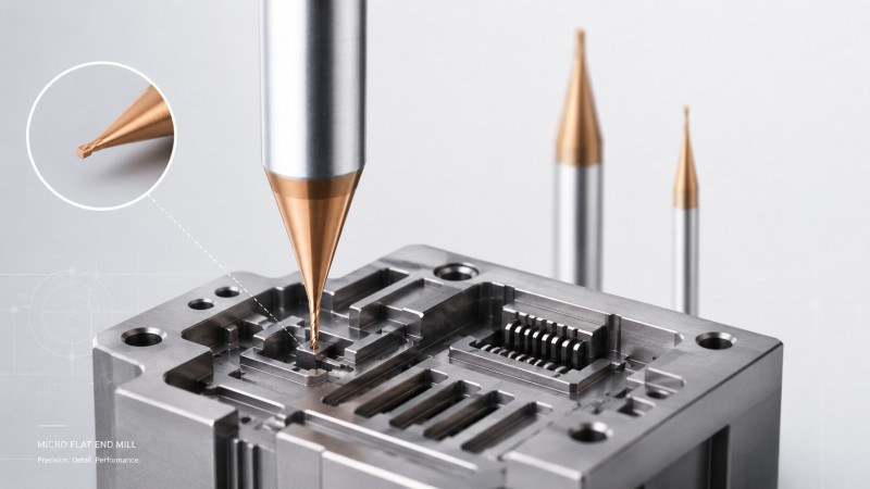
Micro flat end mills are used for narrow slots, small cavities, flat-bottom features, precision shoulders, connector details, and other fine CNC structures where standard-size cutters cannot reach. Choosing the right cutter requires more than matching the diameter to the drawing: flute length, neck clearance, tool overhang, runout, workpiece material, and finishing strategy all affect machining accuracy and tool life.
Small slots, narrow grooves, miniature cavities, flat-bottom pockets, connector openings, precision shoulders, and compact internal features often require a cutter much smaller than a conventional end mill. In these applications, the tool must not only fit the geometry but also maintain enough rigidity and cutting-edge stability to produce the required dimensions and surface quality.
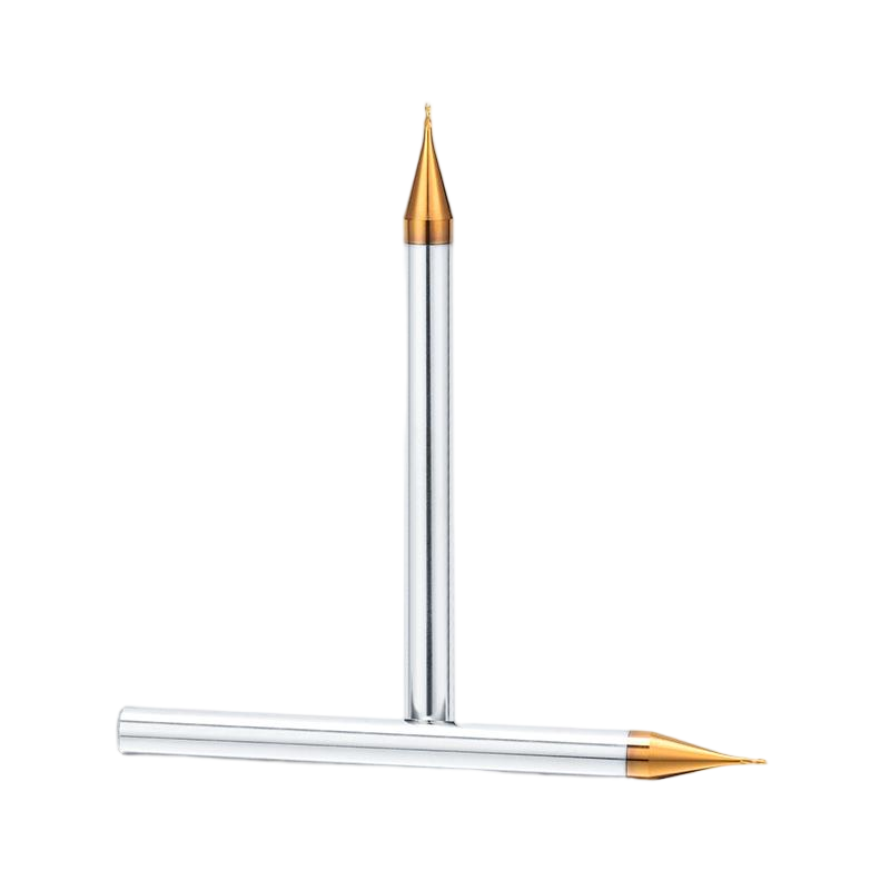
A micro flat end mill is designed for these small-scale machining tasks. Its flat cutting end is suitable for features where a flat bottom, defined sidewall, controlled slot width, or clear bottom-to-wall transition is required.
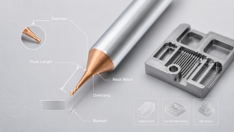
However, choosing the smallest available cutter is not always the best solution. Cutter diameter, flute length, neck length, holder overhang, runout, workpiece material, flute geometry, and chip evacuation should be considered together before the machining parameters are finalized.
For a broader explanation of micro-tool diameter, flute length, neck length, and runout, see our guide on how to choose a micro end mill.

What Is a Micro Flat End Mill?
A micro flat end mill is a small-diameter solid carbide milling cutter with a flat cutting end. Unlike a ball nose cutter, which produces a curved contact profile, a flat end mill is designed to generate a flat bottom while also machining vertical or near-vertical sidewalls.
Typical applications include:
• Micro slots and narrow grooves.
• Small flat-bottom cavities.
• Precision shoulders and steps.
• Small connector and interface features.
• Compact pockets and recessed details.
• Fine trimming and contour machining.
• Small mold details and precision insert features.
The flat-end geometry makes this cutter particularly useful when the bottom surface itself is part of the dimensional or functional requirement.

Is a Micro Flat End Mill the Same as a Micro-Diameter Flat Head End Mill?
Customers may use several different terms when searching for the same basic cutter type, including “micro flat end mill,” “micro-diameter flat head end mill,” “micro flat milling cutter,” and “small-diameter flat end mill.”
In most cases, these searches refer to a small-diameter end mill with a flat cutting end. “Micro flat end mill” is the clearer professional product description, while “flat head end mill” is also commonly used in customer searches.
Regardless of the terminology, the important dimensions remain the same: cutting diameter, flute length, neck dimensions when applicable, shank diameter, overall length, and actual tool overhang after installation.
When Should You Use a Micro Flat End Mill?
The first question should not be “How small can the cutter be?” but “What geometry must the cutter produce?”
| Feature | Why a Micro Flat End Mill May Be Suitable |
|---|
| Narrow slot | Produces a controlled slot bottom and defined sidewalls |
| Flat-bottom cavity | Creates a flat base where a ball nose profile would be unsuitable |
| Small shoulder | Machines the bottom and sidewall transition of a compact step |
| Connector opening | Provides access to small rectangular or slot-type features |
| Small mold detail | Allows local machining where a standard-size cutter cannot reach |
| Flat precision surface | Suitable when bottom flatness and dimensional consistency are important |
How to Choose the Micro Flat End Mill Diameter
The cutter must fit the narrowest required feature, but using the smallest possible diameter usually reduces machining stability.
Whenever the drawing permits, use the largest practical cutting diameter. A larger micro cutter generally provides:
• A larger carbide cross-section.
• Greater resistance to bending.
• Better cutting-edge support.
• More available flute space.
• Lower sensitivity to the same amount of spindle or holder runout.
For example, if a small cutter is required only to clean an internal corner, it is normally more efficient to rough the main cavity with a larger cutter and use the micro flat end mill only for the remaining restricted material.
Should the Cutter Diameter Equal the Final Slot Width?
Not always. A cutter with the same nominal diameter as the slot can machine both walls simultaneously, but the final slot size then depends heavily on the actual cutter diameter, tool runout, spindle condition, deflection, cutting-edge wear, and thermal stability.
For a less critical slot, full-width cutting may be acceptable when the process is stable. For a precision slot, a slightly smaller cutter may provide more control by allowing separate finishing of the two sidewalls.
Before choosing either strategy, consider:
• Final slot-width tolerance.
• Available finishing allowance.
• Measured tool runout.
• Cutter deflection at the required depth.
• Chip evacuation in a full-width slot.
• Whether the material tends to form burrs or adhere to the cutting edge.
Choose the Shortest Practical Flute Length
Flute length is the axial section that actively cuts material. A flute that is much longer than the feature depth does not normally improve machining access; instead, it increases the flexible cutting section of the tool.
For shallow micro slots and cavities, a short cutting section helps maintain rigidity. The standard Dohre micro flat end mills from 0.2 mm to 0.9 mm use compact flute lengths of approximately twice the cutting diameter.
| Cutting Diameter | Standard Flute Length |
|---|
| 0.2 mm | 0.4 mm |
| 0.3 mm | 0.6 mm |
| 0.4 mm | 0.8 mm |
| 0.5 mm | 1.0 mm |
| 0.6 mm | 1.2 mm |
| 0.7 mm | 1.4 mm |
| 0.8 mm | 1.6 mm |
| 0.9 mm | 1.8 mm |
These dimensions are standard options rather than universal recommendations. The required cutting depth and surrounding geometry should determine whether the standard flute length is suitable for the actual feature.
When Do You Need a Long-Neck Micro Flat End Mill?
A deeper feature does not always require a longer cutting edge. When only the bottom or a local section must be machined, a short flute combined with a reduced neck may provide the necessary reach.
A long-neck micro flat end mill may be considered for:
• A small flat feature at the bottom of a deep cavity.
• A narrow groove below a surrounding wall.
• A small connector detail behind a shoulder.
• A recessed mold or electronic component feature.
• A local finishing area where the larger shank cannot enter.
The neck should be only as long and as small in diameter as necessary. Excessive neck length reduces tool rigidity and increases sensitivity to cutting force.
Our guide to long-neck vs long-flute micro end mills explains when additional cutting length is required and when only clearance is needed.
Keep Tool Overhang as Short as Possible
Even a correctly selected micro cutter can become unstable if too much of the tool extends from the holder.
Actual overhang is the unsupported distance between the holder and the cutting tip. As this distance increases, the cutter becomes more sensitive to:
Clamp the tool as deeply as the feature and holder geometry allow rather than using the maximum possible extension.
Why Runout Matters More as the Cutter Gets Smaller
Runout causes the cutting edges to rotate at different effective radii. One flute may therefore remove more material than the other cutting edges.
For a micro flat end mill, this can lead to:
• Unequal flute loading.
• Rapid wear on one cutting edge.
• An oversized slot.
• Different surface quality on opposite walls.
• Corner chipping.
• Unexpected cutter breakage.
Runout should be checked as close to the cutting edge as the measurement method permits. The spindle interface, holder, collet, tool shank, and all contact surfaces should be clean before the measurement is made.
How Workpiece Material Changes Micro Flat End Mill Selection
The correct cutter structure depends not only on feature size but also on the workpiece material. A micro flat end mill used for aluminum may require different cutting-edge geometry, flute space, and coating from a cutter used for stainless steel or mold steel.
| Material | Common Micro-Milling Challenge | Tool Selection Priority |
|---|
| Aluminum | Built-up edge, chip adhesion, burrs, and flute blockage | Sharp edge, smooth chip flow, low cutting resistance, and sufficient flute space |
| Copper alloys | Smearing, ductile burrs, and surface scratching | Sharp cutting edge, low friction, low runout, and controlled evacuation |
| Stainless steel | Heat, work hardening, edge wear, and vibration | Stable edge support, suitable coating, controlled engagement, and short overhang |
| Mold steel | Higher cutting resistance, edge wear, and corner chipping | Carbide substrate, coating, corner strength, rigidity, and material hardness |
| Graphite | Abrasive wear and fine dust | Wear resistance, suitable coating, edge quality, and dust evacuation |
For harder mold materials, cutter rigidity and edge support become particularly important. Our guide to micro end mills for HRC50–60 mold steel explains the additional considerations for small features in heat-treated mold components.
Two Flutes or Four Flutes for a Micro Flat End Mill?
Flute count changes the amount of chip space, the carbide core, the number of active cutting edges, and the frequency at which the edges pass through the material.
The choice should be based on the material and machining operation rather than flute count alone.
| Flute Count | Typical Advantage | Main Consideration |
|---|
| 2 flutes | More flute space for chips | Useful where evacuation is difficult or cutting resistance should remain low |
| 4 flutes | More cutting edges and potentially stronger core support in suitable designs | Reduced flute space must still be sufficient for the material and engagement |
A narrow full-width slot and a light side-finishing pass place very different demands on the cutter, even when the tool diameter is the same.
Chip Evacuation in Narrow Micro Slots
A narrow slot leaves very little space around the cutter. Chips that do not leave the cutting zone may be cut again, trapped against the flute, or dragged across the finished bottom and sidewalls.
Common results include:
• Flute blockage.
• Increasing cutting force.
• Surface scratches.
• Material adhesion.
• Secondary burr formation.
• Unexpected cutting-edge overload.
Select sufficient flute space, direct air or coolant toward the cutting area, and avoid excessive axial engagement that prevents chips from leaving the slot.
How to Reduce Corner Chipping on a Micro Flat End Mill
The outside corner of a flat end mill is an important cutting area because it creates the bottom-to-wall transition. It can also become a local stress point when the cutter enters a heavy corner or encounters interrupted material.
To reduce corner chipping:
• Avoid sudden full radial engagement.
• Do not leave excessive residual material in an internal corner.
• Control tool runout.
• Keep tool overhang short.
• Use cutting-edge geometry and coating suited to the material.
• Replace the tool before progressive wear becomes severe.
If the cutter repeatedly breaks or chips, the failure should be diagnosed before simply reducing all cutting parameters. See why micro end mills break for a more detailed troubleshooting process.
Rough with a Larger Cutter and Finish with the Micro Flat End Mill
A micro flat end mill should normally remove only the material that requires its small diameter. Using it to machine the complete volume of a large cavity increases machining time, chip volume, tool engagement, and failure risk.
A more efficient sequence is:
1. Rough the main cavity with a larger cutter. Remove most of the material with greater rigidity and chip capacity.
2. Leave controlled finishing stock. Avoid leaving large isolated areas of material in small corners.
3. Use the micro flat end mill for restricted features. Machine the final narrow slot, small shoulder, compact cavity, or internal corner.
4. Use a separate finishing pass where accuracy is critical. Keep the remaining cutting load more consistent.
5. Clear chips before final finishing. Prevent roughing chips from damaging the precision surface.
Micro Flat End Mill vs Ball Nose End Mill
These two cutter types are designed for different surface geometries.
| Feature | Micro Flat End Mill | Micro Ball Nose End Mill |
|---|
| Flat-bottom slot | Recommended starting geometry | Not ideal for producing a flat bottom directly |
| Small shoulder | Suitable | Usually not the first choice |
| 3D curved surface | Limited | Better suited to curved contour finishing |
| Curved cavity bottom | Not intended to reproduce the curve | Suitable |
| Defined bottom-to-wall transition | Suitable where the drawing requires a flat-bottom geometry | Produces a radius based on the ball geometry |
If the feature combines flat and curved surfaces, more than one cutter geometry may be required rather than trying to machine the complete part with a single tool.
Standard Dohre Micro Flat End Mill Sizes
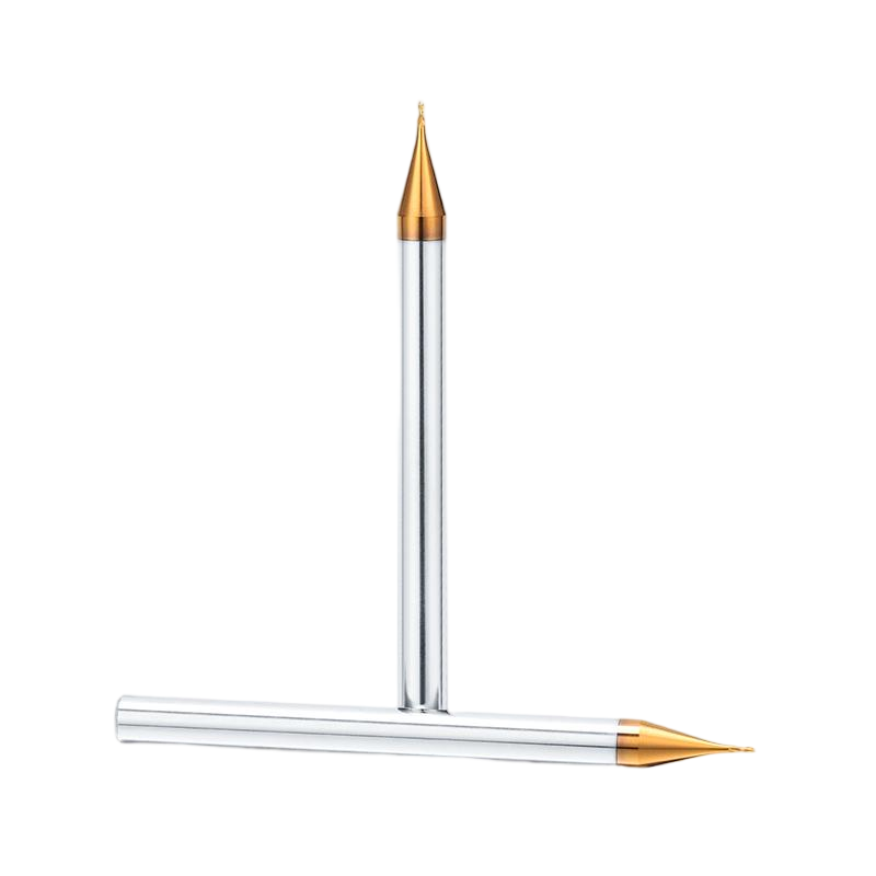
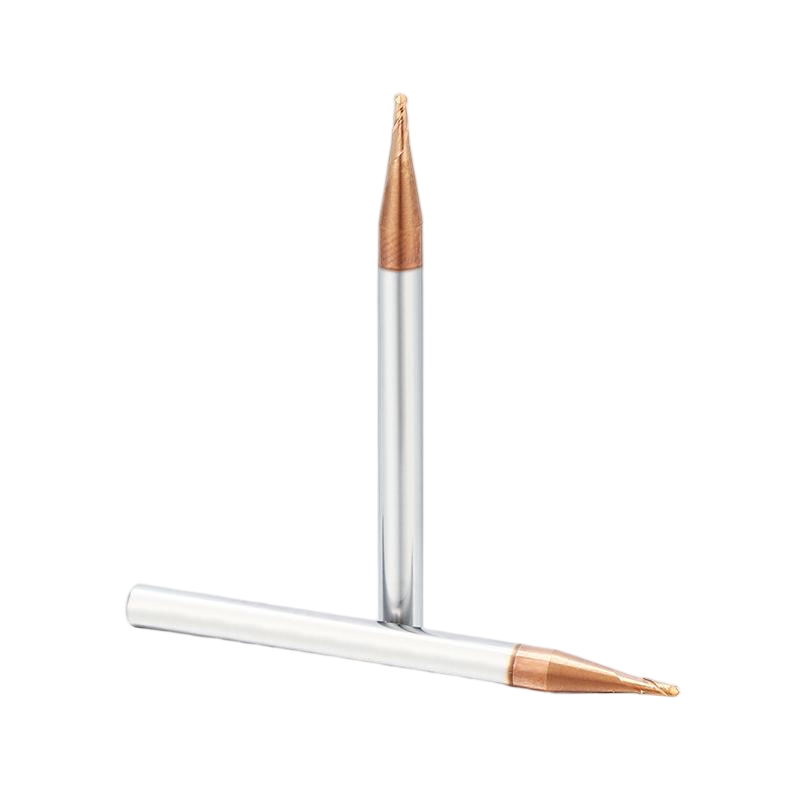
Dohre standard solid carbide micro flat end mills are available with cutting diameters from 0.2 mm to 0.9 mm. The listed tools use a 50 mm overall length and are available with 3 mm or 4 mm shank diameters.
Standard size selection includes:
| Cutting Diameter | Flute Length | Overall Length | Shank Options |
|---|
| 0.2–0.9 mm | 0.4–1.8 mm | 50 mm | 3 mm / 4 mm |
The cutter can also be specified with different carbide grades, coatings, and cutting-edge geometries according to the workpiece material and machining requirement.
When Do You Need a Custom Micro Flat End Mill?
Standard diameters and flute lengths are suitable for many small features, but a custom tool may provide a better match when the component geometry requires unusual reach, clearance, or dimensions.
Custom micro flat end mills may be considered when you need:
• A cutting diameter not available in the standard range.
• A special flute length.
• A short flute combined with an extended reduced neck.
• A specific neck diameter for restricted clearance.
• A different shank diameter or overall length.
• A specific flute number.
• A material-specific coating.
• Application-specific cutting-edge geometry.
For a custom recommendation, the most useful information includes the feature drawing, cutting diameter, machining depth, workpiece material, required tolerance, surface-finish target, toolholder condition, and expected production quantity.
Practical Micro Flat End Mill Selection Checklist
1. Confirm the workpiece material. Tool geometry and coating should match the actual material.
2. Identify the smallest feature. Confirm slot width, pocket width, shoulder position, and internal corner size.
3. Select the largest practical diameter. Avoid making the cutter smaller without a geometric reason.
4. Determine the active cutting depth. Choose only the flute length required to cut the feature.
5. Check neck clearance. Use a reduced neck only if the surrounding geometry requires additional reach.
6. Keep actual overhang short. Clamp the tool as deeply as the application allows.
7. Select the flute count. Balance chip space, tool core, engagement, and workpiece material.
8. Plan chip evacuation. Make sure chips can leave narrow slots and cavities.
10. Measure runout. Check close to the cutting edge after the tool is installed.
11. Use a larger cutter for bulk removal. Reserve the micro tool for the geometry that actually requires it.
12. Inspect the first features. Check slot width, bottom quality, sidewall finish, burrs, and tool condition.
FAQ
What is a micro flat end mill used for?
A micro flat end mill is used for narrow slots, small cavities, flat-bottom pockets, precision shoulders, grooves, connector details, and other fine features that require a small cutting diameter and a flat bottom.
Is a micro flat end mill the same as a flat head end mill?
The terms are often used to describe the same basic cutter type: a small-diameter end mill with a flat cutting end. “Micro flat end mill” is a clearer professional description, while “micro-diameter flat head end mill” may also appear in customer searches.
What diameters are available for Dohre micro flat end mills?
The current standard range includes cutting diameters from 0.2 mm to 0.9 mm. Other cutting diameters can be customized according to the feature requirement.
Should the micro end mill diameter equal the slot width?
Not necessarily. A same-size cutter can machine both slot walls simultaneously, but critical slot width may be easier to control with a slightly smaller cutter and separate finishing passes when the feature permits.
How should I choose the flute length?
Choose the shortest flute length that safely covers the active cutting depth. A flute that is much longer than necessary increases the flexible section of the tool and may increase deflection.
When should I use a long-neck micro flat end mill?
A long-neck design may be useful when a small feature is located below a surrounding wall or shoulder but only a short section near the tip needs to cut material. The reduced neck provides clearance behind the cutting edge.
Why does a micro flat end mill produce an oversized slot?
Possible causes include runout, cutter deflection, cutting-edge wear, excessive overhang, spindle movement, or using a full-width tool without a controlled finishing strategy.
Can a micro flat end mill machine aluminum and stainless steel?
Micro flat end mills can be designed for different materials, but the same tool geometry should not automatically be used for every material. Carbide grade, coating, flute geometry, flute count, edge preparation, and cutting conditions should be matched to the workpiece.
When is a custom micro flat end mill needed?
A custom cutter may be useful when the application requires a non-standard cutting diameter, special flute length, extended reduced neck, specific neck diameter, different shank size, special coating, flute number, or application-specific geometry.
Conclusion
Choosing a micro flat end mill starts with the actual feature rather than the smallest available cutter diameter. The tool must fit the slot, cavity, shoulder, or flat-bottom detail while retaining as much rigidity as the geometry allows.
Use the largest practical cutting diameter, the shortest suitable flute length, only the neck reach required for clearance, and the minimum practical holder overhang. Workpiece material, flute count, coating, runout, chip evacuation, and machining strategy should then be matched to the application.
For larger cavities, remove the bulk material with a more rigid cutter and reserve the micro flat end mill for the narrow slots, small corners, flat-bottom details, and precision features that actually require its small diameter.
Dohre provides solid carbide micro flat end mills in standard diameters from 0.2 mm to 0.9 mm as well as custom sizes, flute lengths, neck dimensions, shank sizes, coatings, flute numbers, and application-specific geometries. Contact us with your workpiece material, feature drawing, cutter diameter, machining depth, tolerance, surface requirement, and production quantity for tool recommendations.