


Learn how to select and match milling tools for mold steel roughing and finishing. Discover expert strategies on tool geometry, coatings, and overhang control to prevent tool wear and improve surface finish.


Reading volume: 156

Release time :2026-08-17
Estimated reading time:
Learn how to select and match milling tools for mold steel roughing and finishing. Discover expert strategies on tool geometry, coatings, and overhang control to prevent tool wear and improve surface finish.
Mold steel machining presents a constant balance between metal removal speed and surface quality. When working with difficult materials like hardened die steel, choosing the wrong end mill leads to high tooling costs, excessive vibration, and sudden tool breakage.
Machine shops often lose profits due to poor surface finishes that require hours of expensive manual bench polishing.Selecting the right cutting tool combination for roughing and finishing solves these production bottlenecks.
Matching tool substrate, coating, and geometry to specific mold materials ensures predictable tool life and maintains required tolerances. This technical guide outlines actionable strategies to match milling tools to your mold steel applications efficiently.
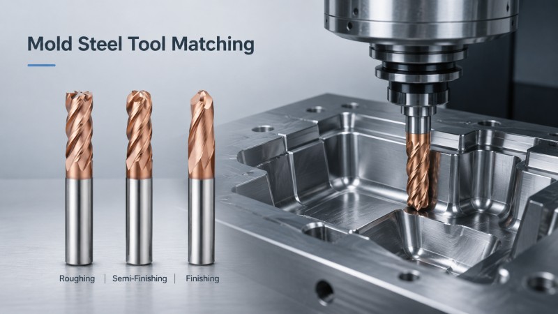
Pre hardened steels typically fall within 28 to 38 HRC. These materials offer good machinability, but they easily cause built up edge if cutting speeds are inappropriate. Standard carbide grades with high toughness perform well here. Tool geometry should emphasize sharp cutting edges and polished flutes to promote smooth chip clearance during extended roughing passes.
Hardened die steels ranging from 45 to 60 HRC generate extreme heat and severe mechanical stress during cutting. Machining these alloys requires end mills built from micro grain carbide substrates with high cobalt content. Using high performance solid carbide end mills provides the necessary rigidity to prevent edge chipping under heavy loads.
To simplify your tool selection process, the following comparison highlights recommended tool types based on material hardness and target applications.
| Mold Steel Material | Typical Hardness | Primary Application | Recommended Geometry and Coating |
|---|---|---|---|
| P20 or 718H | 28 to 38 HRC | Plastic injection molds and general bases | Square or Corner Radius; AlTiN Coating |
| H13 or SKD61 | 45 to 55 HRC | Hot work dies and die casting cavities | Corner Radius or High Feed; TiAlSiN Coating |
| S136 | 48 to 54 HRC | Mirror plastic molds and medical tools | Ball Nose End Mills; Sub Micron Carbide |
| CPM Powder Steel | 55 to 60 HRC | High wear punch dies and stamping tools | Corner Radius; HIPIMS Nano Coated End Mills |
Having established how material hardness determines base tool selection, the next step involves matching tool geometry to specific machining operations.
Roughing operations focus on maximizing metal removal rates without sacrificing machine stability. High feed cutters feature shallow entering angles that direct cutting forces axially into the machine spindle. Utilizing a dedicated end mill for mold steel allows high feed rates during deep cavity roughing while minimizing lateral deflection.
Finishing curved mold contours requires precise profile accuracy and low surface roughness. Ball nose end mills process complex surfaces through fine stepovers. Maintaining low radial runout ensures consistent tooth engagement, preventing gouging marks and drastically reducing post machining polishing time on final mold surfaces.
Corner radius end mills offer a stronger cutting edge than standard square end mills. They distribute heat and mechanical stress across the radius, reducing corner chipping during semi finishing operations. This configuration handles shoulder transitions reliably, extending tool life across demanding Milling Tools for Mold and Die applications.
While optimized geometries establish mechanical stability, managing high cutting temperatures requires advanced surface coatings.
Machining hard mold materials generates localized temperatures at the cutting zone exceeding 800 degrees Celsius. Titanium aluminum nitride coatings form a protective aluminum oxide layer when exposed to heat. This layer acts as a thermal barrier, preserving substrate hardness and delaying flank wear during aggressive dry milling cycles.
High Power Impulse Magnetron Sputtering coating technology produces extremely dense nano composite structures. Coatings applied via this method exhibit superior film adhesion, high oxidation resistance up to 1200 degrees Celsius, and low friction coefficients. These characteristics prevent micro cracking when dry finishing hardened steels up to 60 HRC.
Selecting the proper coating depends directly on operational temperature and material hardness requirements.
Understanding heat generation leads directly to evaluating cutting environments and vibration control strategies.
Applying liquid flood coolant during high speed milling of hardened steel causes rapid thermal expansion and contraction. This thermal cycling creates micro cracks perpendicular to the cutting edge, leading to sudden tool failure. Utilizing high pressure air blast removes chips effectively while keeping cutting zone temperatures predictable without thermal shock.
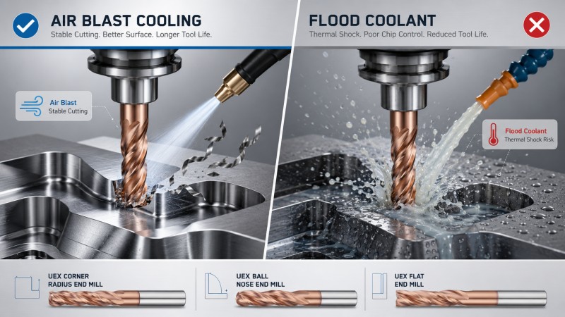
Deep mold cavities require long tool overhangs, which increase susceptibility to chatter. Keeping the length to diameter ratio under four times diameter prevents excessive vibration. When longer reach is unavoidable, specialized end mills featuring variable helix angles and unequal flute spacing disrupt harmonic resonance, maintaining clean surface finishes on your workpiece.
Before reaching a final decision on your tool purchasing path, reviewing common shop floor questions helps prevent costly processing mistakes.
Custom tool pricing depends on raw material grain size, specialized PVD coating types, complex custom geometries, and total batch volume. Custom grinding setup times also affect unit prices for non-standard tools. For accurate pricing based on your specific mold machining requirements, contact the Dohre CNC Tools engineering team directly.
Using low precision collet chucks with high runout causes uneven chip loading across the tool flutes. If one flute takes a heavier cut than the others, it wears prematurely and causes chatter. Precision shrink fit or hydraulic holders keeping runout below 0.003 mm are essential for maximum tool life.
Operators should monitor flank wear width using an optical loop during tool pauses. A uniform flank wear band up to 0.2 mm indicates normal wear. If micro chipping appears along the cutting edge or acoustic monitoring detects unusual spindle noise, the tool should be replaced before catastrophic failure occurs.
Matching the right end mill to specific mold steel properties directly improves machining productivity and lowers operational overhead. Selecting appropriate geometries for roughing, semi finishing, and finishing operations minimizes tool wear, prevents thermal cracking, and eliminates costly manual bench work. Adopting proper tool overhang controls and dry air blast strategies further secures stable CNC processing.
Partnering with an experienced tool manufacturer ensures access to consistent tool quality and custom engineering support. Dohre CNC Tools delivers high performance solid carbide end mills engineered for rigorous die and mold manufacturing. Reach out to our technical support team today to optimize your tooling strategies and request a competitive quote.
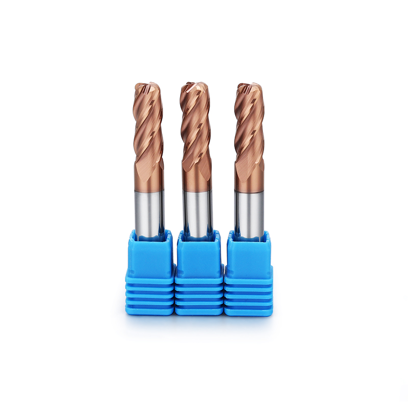
• Ultra-fine submicron carbide (
Learn More>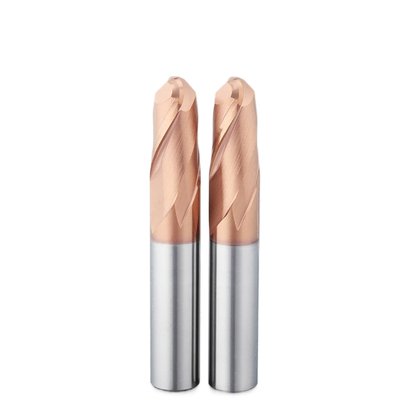
• Extra-fine submicron carbide (grain
Learn More>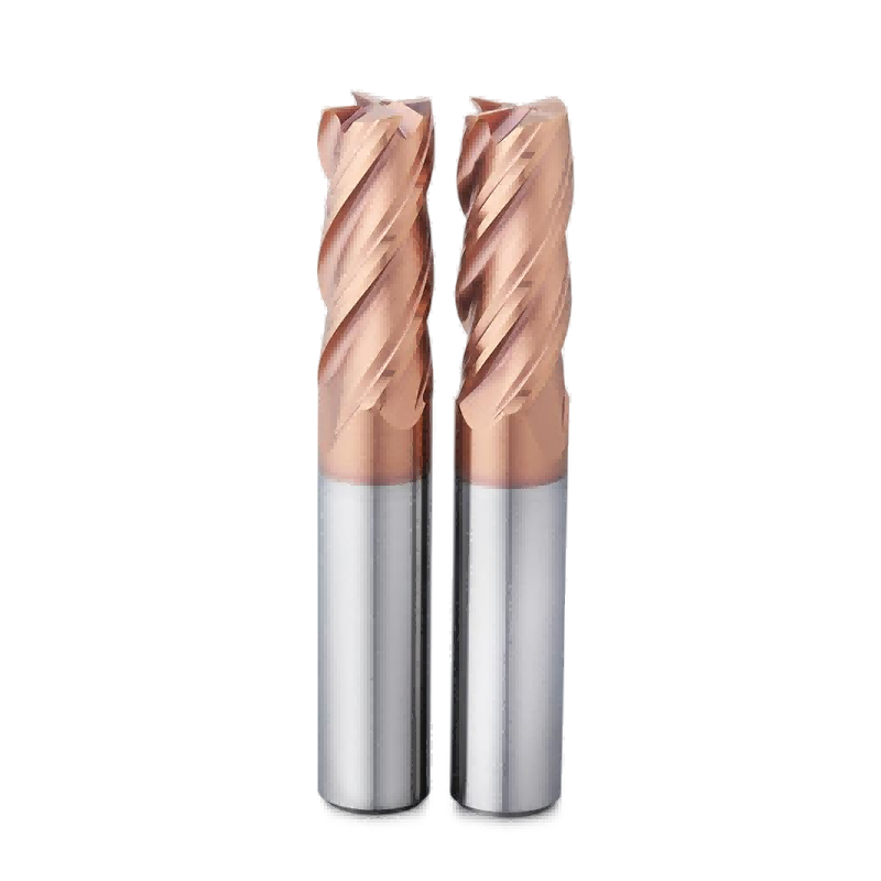
• Ultra-fine carbide grain
Learn More>By continuing to use the site you agree to our privacy policy Terms and Conditions.