How to Reduce Burrs and Thin-Wall Deformation in Cold Plate Milling
Introduction
Cold plates often combine narrow flow channels, thin separating walls, precision edges, and sealing surfaces in one component. Burr formation and wall deformation can affect channel dimensions, plate flatness, assembly, cleaning, and sealing reliability. This guide explains how tool condition, cutting direction, engagement, workholding, and machining sequence influence these problems.
Server cold plates often contain narrow flow channels separated by thin walls. The same component may also include inlet and outlet areas, mounting holes, internal pockets, sealing surfaces, and external profiles.
These features make burr control and dimensional stability closely related. A cutting condition that produces excessive burrs may also place too much force on a thin wall. A wall that deflects during machining can change the effective cutting engagement and create additional burrs, uneven channel width, or poor surface quality.
Reducing these problems requires more than lowering the feed rate. Tool sharpness, runout, cutter diameter, cutting direction, entry and exit position, workholding, remaining allowance, and machining sequence all influence the final result.
Why Burrs and Thin-Wall Deformation Often Occur Together
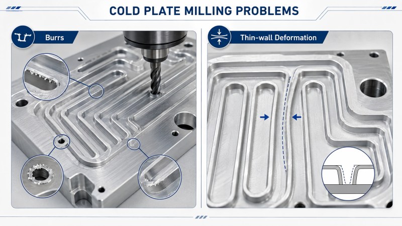
A thin channel wall has less support than a solid section of material. When the end mill applies radial cutting force, the wall may move away from the cutting edge instead of remaining in its programmed position.
This movement changes the actual chip thickness. The cutter may rub along part of the wall and then remove more material when the wall springs back. The result can include a tapered channel, uneven sidewall, rolled edge, visible tool marks, or a burr at the top of the wall.
Burrs become more severe when the cutting edge is worn, the tool exits through an unsupported edge, or chips remain between the cutter and the workpiece. Thin-wall accuracy and edge quality should therefore be controlled as one machining problem rather than two separate defects.
| Observed Problem | Possible Cause | What to Check |
|---|
| Burr along the entire channel edge | Worn edge, excessive runout, rubbing, or unsuitable geometry | Tool condition, runout, feed per tooth, and workpiece material |
| Burr concentrated at the channel exit | Abrupt breakout through an unsupported edge | Toolpath direction, exit position, and edge support |
| Channel width changes from top to bottom | Tool deflection or thin-wall movement | Tool overhang, radial engagement, wall thickness, and cutting sequence |
| Plate becomes distorted after unclamping | Excessive clamping force or unbalanced material removal | Fixture support, clamping position, and machining order |
| Scratched channel walls or sealing surfaces | Chip recutting or chips trapped under the cutter | Chip evacuation, coolant direction, and channel cleanliness |
Where Burrs Commonly Form on a Cold Plate
Burr location provides useful information about the cutting process. Instead of treating every burr with the same solution, identify where it forms and which cutting edge created it.
Along the Top Edge of a Flow Channel
A burr along the full channel edge may indicate that the material is being pushed or smeared rather than cut cleanly. Common causes include a dull cutting edge, excessive runout, unstable wall support, or a cutter geometry that does not match the material.
At Channel Entrances and Exits
The cutter may enter or leave the material near a weak edge, connector area, or thin wall. Abrupt breakout can bend the remaining material and leave a larger burr than the rest of the channel.
Around Ports and Mounting Features
Ports, mounting holes, pockets, and intersecting features may create interrupted cutting. The cutting edge repeatedly enters and exits the material, which can increase vibration and produce local burrs around the feature boundary.
On Sealing and Mating Surfaces
Small burrs or raised edges on a sealing surface can increase cleaning and finishing work. They may also affect the contact between the cold plate and its cover, gasket, or mating component.
Copper and Aluminum Produce Different Burr Behavior
Copper and aluminum are both ductile materials, but their cutting behavior is not identical. Tool selection and burr-control methods should follow the actual alloy and component design.
| Machining Factor | Aluminum Cold Plate | Copper Cold Plate |
|---|
| Typical burr form | Rolled edge, exit burr, or material pulled by built-up edge | Ductile burr, edge smearing, or fine residual material |
| Common tool-related cause | Built-up edge, chip packing, or insufficient flute space | Dull edge, adhesion, rubbing, or chip recutting |
| Edge requirement | Sharp edge with low cutting resistance | Very sharp edge for clean shearing |
| Flute requirement | Large chip space and polished evacuation path | Smooth flute and controlled chip movement |
| Main thin-wall concern | Low stiffness, internal stress, and sensitivity to clamping | Local deflection, ductile edge movement, and heavy component mass |
A detailed material comparison is available in our guide to copper versus aluminum server cold plate machining.
Start with a Sharp and Material-Specific Cutting Edge
A sharp edge reduces the amount of material that is pushed ahead of the cutter. This is important when machining ductile materials and unsupported channel walls.
As the edge wears, cutting pressure increases. The tool may continue producing parts, but the channel edge may begin to roll, smear, or develop a larger burr. Waiting until the tool fails completely is usually too late for precision cold plate production.
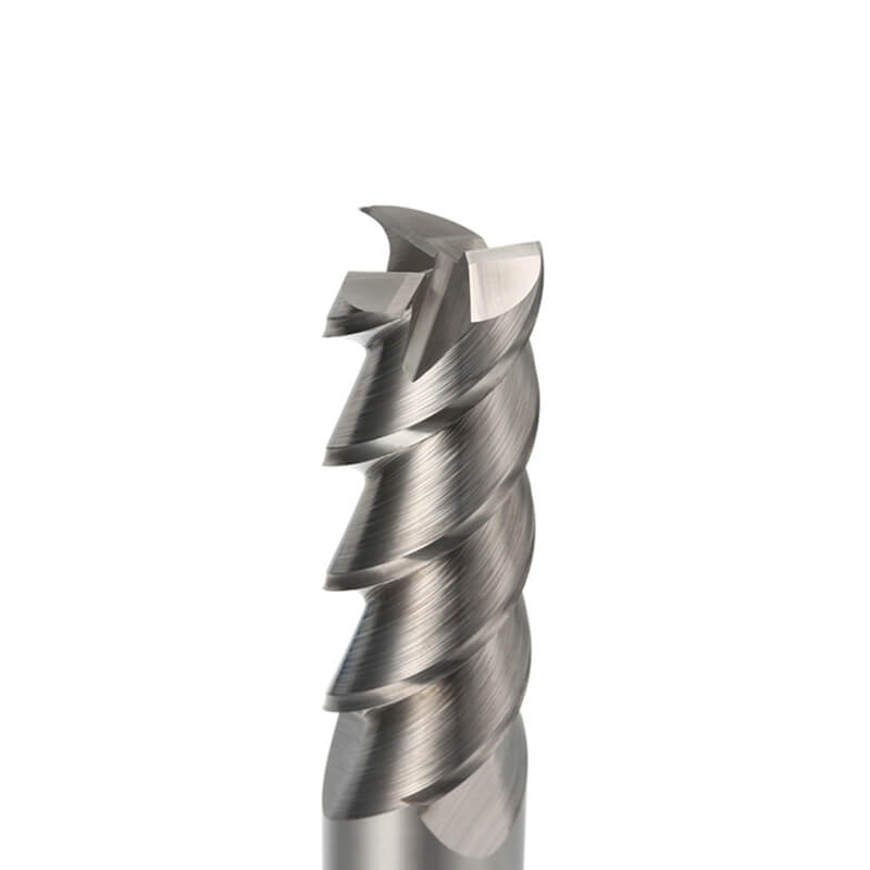
For aluminum components, a sharp edge combined with a smooth or polished flute helps reduce built-up edge and supports chip evacuation. Dohre AEX aluminum end mills are designed for aluminum slotting, pocketing, side milling, profiling, and surface-finishing applications.
Copper alloys may require a different edge and flute solution. The tool should shear cleanly, limit adhesion, and prevent copper chips from being dragged across the finished surface.
Control Runout Before Adjusting the Feed Rate
Excessive runout causes one flute to remove more material than the others. The overloaded edge wears faster and may produce a larger burr on one side of the channel.
Runout also increases the effective cutting diameter and may produce an oversized channel. On a small-diameter cutter, even a small runout value represents a significant percentage of the tool diameter.
Before reducing the feed, inspect the collet, holder, spindle interface, tool clamping length, and cleanliness of the contact surfaces. Runout should be measured close to the cutting edge rather than only on the shank.
Use the Largest Practical Cutter Diameter
A small cutter may be required by the channel width or internal corner, but selecting a diameter smaller than necessary reduces rigidity and increases deflection.
Use the largest cutter that can produce the required feature. When a small radius exists only in limited areas, rough the main channel with a larger tool and use a smaller cutter only for the remaining corners.
This approach reduces cutting time with the weakest tool and helps maintain more consistent wall position and channel width.
Keep Cutting Length and Tool Overhang as Short as Possible
Long cutting length and excessive tool overhang increase bending. A deflected tool may leave a tapered wall, inconsistent channel width, or burrs that change from the top to the bottom of the feature.
The cutting length should match the material that the flute must actually remove. For deeper access, a reduced-neck cutter can provide clearance while keeping the cutting edge shorter and more rigid.
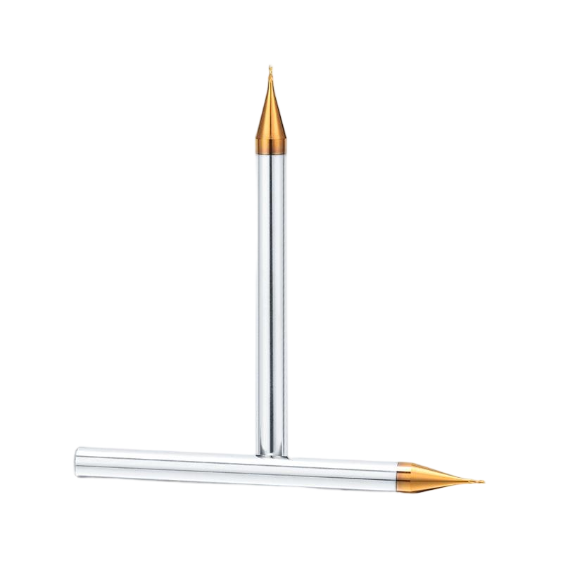
A solid carbide micro-diameter end mill can be selected for narrow channels and small cold plate features when the diameter, cutting length, neck reach, and flute geometry are matched to the application.
Plan the Cutting Direction and Tool Exit
Burr formation is often related to the direction in which the cutting edge leaves the material. An unsupported edge may bend outward during breakout instead of being cut cleanly.
Where the geometry allows, direct the final tool exit toward a supported region rather than a thin wall or open edge. Avoid ending the cutting path at the weakest point of the channel.
Climb or conventional milling should not be selected by a single universal rule. The correct direction depends on the material, wall position, machine condition, cutter geometry, and which side of the feature is most sensitive to burr formation.
Avoid Abrupt Full-Width Engagement Near Thin Walls
Sudden full-width engagement places a high load on a small cutter and the surrounding wall. It may also trap chips between both sides of the tool and the channel.
Progressive depth, ramping, helical entry, or a pre-machined entry area can reduce the initial cutting shock. The entry method should be compatible with the tool geometry and available chip evacuation.
For more detailed guidance on cutter diameter, depth, runout, and chip removal, see how to machine narrow flow channels in server cold plates.
Use Balanced Machining for Adjacent Channels
Machining one channel completely before beginning the adjacent channel may leave the separating wall supported on only one side. The next cutting pass can then push the wall into the empty channel.
A balanced machining sequence removes material more evenly. Rough neighboring channels progressively and leave material on both sides of the wall until the structure is close to its final form.
Semi-finishing can then establish a consistent wall shape before a light finishing pass brings both sides to their final dimensions.
| Machining Approach | Effect on Thin Walls |
|---|
| Complete one channel before machining the next | May leave the wall unsupported and increase deflection |
| Rough neighboring channels progressively | Keeps material support more balanced |
| Leave uniform semi-finishing stock | Creates a more consistent load during final wall finishing |
| Finish both sides under similar conditions | Improves wall position, parallelism, and channel consistency |
Control Workholding Without Distorting the Plate
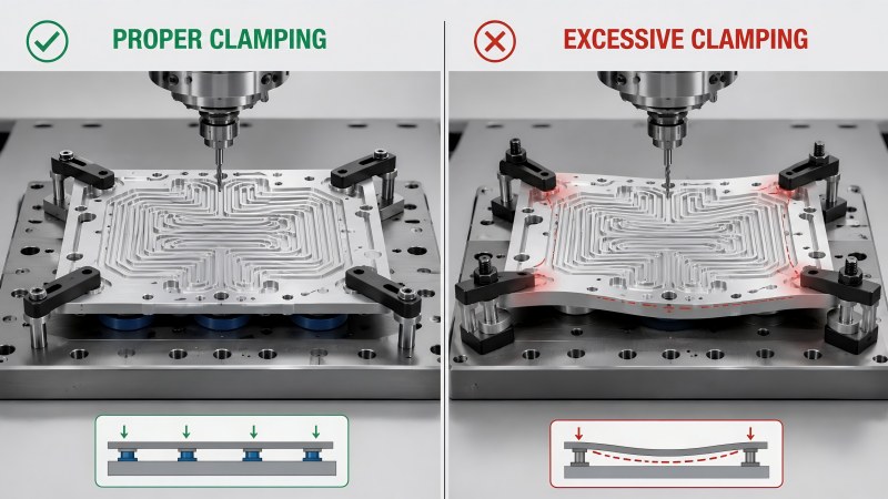
The fixture must support the cold plate against cutting force, but excessive clamping pressure can bend a thin plate before machining begins.
A distorted part may appear flat while it remains clamped. After the fixture is released, the plate can spring back and show flatness error, channel misalignment, or uneven sealing surfaces.
Use distributed support where possible and avoid concentrating clamping force near thin walls or large open areas. The support points should match the material-removal sequence so that the part remains stable throughout the operation.
Separate Roughing, Semi-Finishing, and Finishing
Trying to reach the final wall dimension directly from solid material increases cutting force and makes wall movement more difficult to control.
| Machining Stage | Main Objective | Burr and Deformation Control |
|---|
| Roughing | Remove bulk material efficiently | Use stable engagement and leave enough material for correction |
| Semi-finishing | Create a consistent wall and channel shape | Leave uniform allowance on both sides of thin walls |
| Finishing | Reach final width, wall position, and edge quality | Use a sharp edge, low runout, light engagement, and controlled exit |
| Final inspection | Confirm dimensions, flatness, and cleanliness | Inspect after unclamping and remove residual chips or burrs |
A separate finishing tool is often preferable when edge quality and channel dimensions are critical. A roughing cutter may still remove material, but its worn edge may no longer be suitable for final burr control.
Improve Chip Evacuation to Protect Channel Edges
Chips trapped in a narrow channel may be cut repeatedly. Recut chips increase cutting pressure, damage the channel wall, and create scratches on sealing or contact surfaces.
• Use sufficient flute space for the workpiece material.
• Direct coolant or air into the cutting zone.
• Remove chips between progressive depth passes.
• Keep chips from one channel out of adjacent finished channels.
• Inspect the flute for built-up material or copper adhesion.
• Avoid allowing the tool to dwell while chips remain under the cutting edge.
Use Light Edge Finishing Instead of Aggressive Manual Deburring
Manual deburring may be necessary for some components, but aggressive hand finishing can change channel dimensions, round precision edges, scratch sealing surfaces, or damage thin walls.
Where possible, reduce the burr during CNC machining. A light finishing pass, controlled edge break, or small chamfer can provide more consistent results than removing a large burr after machining.
The edge treatment should still follow the component drawing. A designed chamfer is different from an uncontrolled rounded edge created by manual polishing.
Inspect the Plate After Unclamping
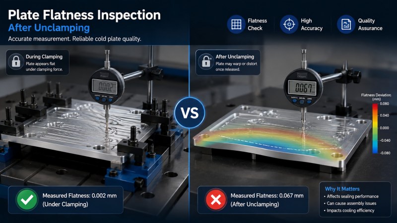
Inspection performed only while the part remains clamped may not reveal the final plate condition. Thin cold plates can move after the fixture pressure is released.
Critical inspection points may include:
• Overall plate flatness.
• Channel width and depth.
• Thin-wall position and parallelism.
• Burrs around channel edges and ports.
• Scratches or recut-chip marks.
• Sealing-surface condition.
• Residual chips inside channels and cavities.
Production inspection should focus on the first characteristic that changes as the tool wears. Depending on the application, this may be burr size, channel width, wall position, flatness, or surface finish.
When Is a Custom End Mill Useful?
A standard end mill may not provide the best combination of rigidity, reach, corner form, and edge geometry for every cold plate design.
A custom cutter may be considered when the component includes:
• A non-standard channel width.
• A deep channel requiring a short flute and extended reduced neck.
• A special wall transition or bottom radius.
• A stepped feature or combined profile.
• Limited holder clearance.
• A material requiring a sharper or application-specific flute geometry.
• A production operation where one tool can replace several standard cutters.
Dohre provides custom and non-standard end mills according to the component drawing, material, channel dimensions, wall thickness, corner requirement, tolerance, and machine conditions.
Practical Checklist for Burr and Deformation Control
• Confirm the cold plate material and alloy.
• Identify the thinnest walls and least-supported edges.
• Use a sharp cutting edge designed for the workpiece material.
• Check runout near the cutting edge.
• Use the largest cutter diameter that fits the feature.
• Keep cutting length, neck length, and total overhang as short as possible.
• Avoid abrupt full-width engagement near unsupported walls.
• Plan the final tool exit away from weak edges where possible.
• Machine adjacent channels in a balanced sequence.
• Leave uniform stock for semi-finishing and finishing.
• Use distributed workholding without excessive clamping force.
• Maintain clear chip evacuation throughout the channel.
• Replace the cutter before burr growth or wall error becomes unacceptable.
• Inspect flatness and critical dimensions after unclamping.
FAQ
Why do burrs form along cold plate flow channels?
Common causes include a worn cutting edge, built-up material, excessive runout, unstable thin walls, poor chip evacuation, and an abrupt tool exit through an unsupported edge.
Will reducing the feed eliminate cold plate burrs?
Not always. Lower feed will not correct a dull tool, excessive runout, poor wall support, chip recutting, or an unsuitable tool exit. The cause of the burr should be identified first.
Why do thin walls move during flow-channel milling?
Thin walls have limited stiffness and may deflect under radial cutting force. Long tool overhang, heavy engagement, unbalanced machining, and excessive clamping pressure can increase the movement.
How can plate distortion after unclamping be reduced?
Use distributed support, avoid excessive clamping force, remove material in a balanced sequence, leave uniform finishing allowance, and inspect the plate again after the fixture is released.
Should neighboring channels be machined one at a time?
Completing one channel before beginning the next may leave the separating wall unsupported. Progressive and balanced machining of neighboring channels often provides better wall stability.
Can the same burr-control method be used for copper and aluminum?
The general principles are similar, but the cutter geometry and process should follow the actual material. Aluminum often requires built-up-edge control and generous chip space, while copper requires very sharp cutting and protection against adhesion and smearing.
When should a custom end mill be considered?
A custom cutter may be useful for non-standard channels, deep narrow features, special radii, limited clearance, combined profiles, or applications where standard tools require excessive reach.
Conclusion
Burr formation and thin-wall deformation in cold plate milling are closely connected. A dull or unstable cutter can increase cutting force, move the channel wall, and leave rolled or smeared edges. Poor support and unbalanced material removal can also distort the complete plate after machining.
A stable process uses a sharp material-specific edge, low runout, the largest practical cutter diameter, limited overhang, controlled engagement, balanced channel machining, and workholding that supports the part without forcing it into a temporary shape.
Dohre provides carbide end mills, aluminum-specific tools, micro-diameter cutters, and custom solutions for cold plate channels, thin walls, sealing surfaces, and precision liquid cooling components. Contact us with your component drawing, material, channel dimensions, wall thickness, tolerance, and machining conditions for tool recommendations.