


Get In Touch
Do you have a questions or an issues we can help you with?
Let’s talk about your project and how Dohre can help get your tools designed, manufactured and ready for the market.


Reading volume: 240

Release time :2026-07-23
Estimated reading time:
Burrs around narrow slots, connector openings, thin edges, and precision cavities can affect optical transceiver housing assembly and increase manual finishing work. This guide explains how tool condition, runout, cutting direction, chip evacuation, workpiece support, and material-specific end mills influence burr formation.
Optical transceiver housings may contain narrow slots, small cavities, connector openings, thin walls, mounting shoulders, positioning features, and thermal contact surfaces. These structures are compact, and even a small burr may affect assembly clearance, damage a nearby precision edge, or increase manual finishing work.
Burr formation is not controlled by feed rate alone. The cutting-edge condition, tool runout, flute geometry, workpiece material, wall support, toolpath direction, chip evacuation, and exit position all influence the final edge quality.
A stable process begins by identifying where the burr appears and which cutting action created it. The correct solution for a burr along the complete slot edge may be different from the solution for a burr concentrated around a connector opening or at the end of a toolpath.
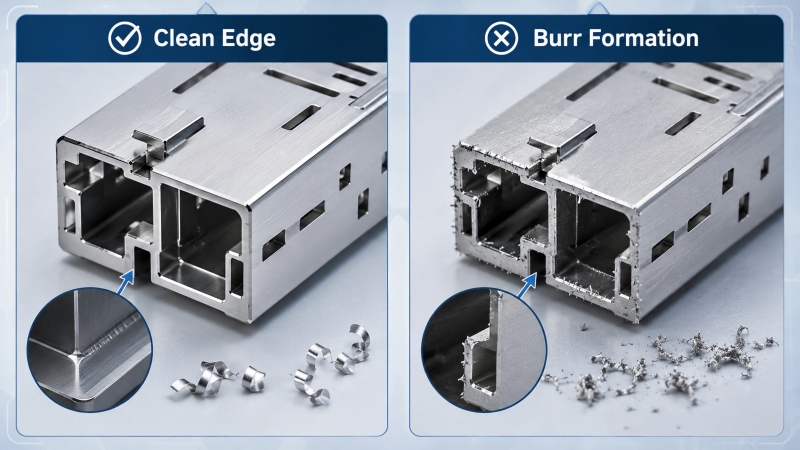
A housing may remain within its main dimensional tolerance while still containing burrs that affect assembly. Small raised edges can interfere with component insertion, reduce clearance around a connector, prevent a cover from sitting correctly, or create loose particles during handling.
Manual deburring can remove visible material, but it may also round a positioning edge, change a narrow-slot dimension, scratch a thermal contact surface, or damage a thin wall. Preventing or reducing the burr during CNC machining is generally more consistent than relying entirely on post-processing.
For a broader overview of housings, thermal parts, alignment features, and precision milling applications, see our guide to end mills for optical transceiver housings and precision components.
The burr location often provides the first indication of its cause. Before changing the cutting parameters, inspect whether the burr appears along the complete feature, on one side only, at the tool exit, or around an interrupted opening.
| Burr Location | Possible Cause | What to Check First |
|---|---|---|
| Along the full slot edge | Worn cutting edge, rubbing, built-up material, or unsuitable cutter geometry | Tool condition, material matching, feed per tooth, and runout |
| On one side of the slot | Unequal flute loading, cutting direction, or wall movement | Runout, milling direction, wall support, and tool deflection |
| At the end of the toolpath | Abrupt exit through an unsupported edge | Exit direction, remaining material, and local edge support |
| Around connector openings | Interrupted cutting, thin edges, or repeated tool entry and exit | Toolpath transitions, edge support, and finishing allowance |
| Around small cavity corners | Tool deflection, chip congestion, or an overloaded small cutter | Cutter diameter, cutting depth, corner engagement, and chip removal |
| On thin housing walls | Wall deflection or insufficient workpiece support | Radial cutting force, clamping, remaining stock, and machining sequence |
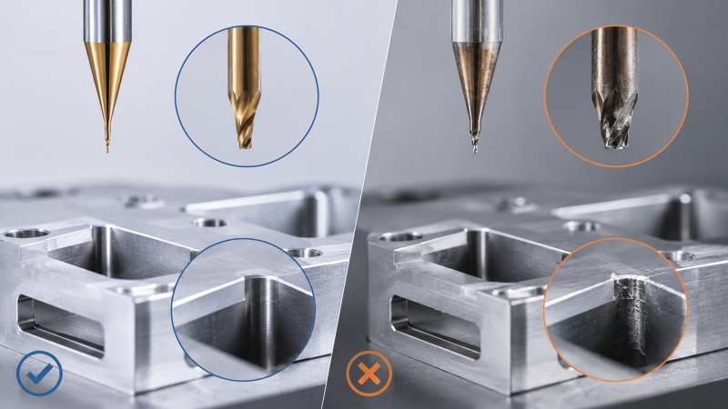
A sharp cutting edge shears the material more cleanly. As the edge wears, more material may be pushed, bent, or smeared ahead of the cutter instead of being removed as a controlled chip.
The end mill may continue cutting after the edge condition has begun to affect the housing. Common early signs include increasing burr height, changing slot width, rougher sidewalls, higher spindle load, irregular chip shape, or material adhering to the flute.
Do not wait for complete tool breakage before replacing a micro end mill. For precision housing production, the tool-change standard should be based on the first critical feature that becomes unacceptable.
Runout causes the cutting edges to follow different paths. One flute may remove most of the material while another flute cuts very little or rubs against the surface.
The overloaded edge wears faster and may produce a larger burr on one side of the slot. Runout can also increase the effective cutting diameter, resulting in an oversized feature or inconsistent wall position.
This problem becomes more important as the tool diameter decreases. Before machining narrow slots or fine openings, inspect the holder, collet, spindle interface, tool clamping length, and cleanliness of all contact surfaces. Runout should be checked near the cutting edge rather than only on the shank.
The smallest available end mill is not automatically the best choice. Reducing the cutter diameter also reduces rigidity and increases sensitivity to runout, bending, chip congestion, and sudden engagement.
Use the largest cutter that can produce the required slot width and internal radius. When a small radius exists only in a limited corner, rough the main cavity or slot with a larger tool and use the smaller cutter only for the remaining material.
This approach reduces the cutting time and load placed on the weakest tool. More information is available in our guide to machining small slots, cavities, and alignment features in optical transceiver housings.
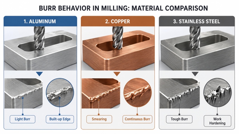
Optical transceiver housings and related components may use different metals according to their structural, thermal, weight, and manufacturing requirements. Burr control begins with a cutter geometry designed for the actual workpiece material.
Aluminum can form built-up edge when material adheres to the cutter. The accumulated material changes the effective cutting geometry and may pull, smear, or roll the housing edge.
A sharp cutting edge, low cutting resistance, sufficient chip space, and a smooth or polished flute help reduce adhesion and support cleaner evacuation. Dohre AEX aluminum end mills are designed for aluminum slotting, pocketing, profiling, side milling, and finishing applications.
Copper and similar materials may smear or form ductile burrs when the cutting edge becomes dull. A very sharp edge, smooth flute surface, low runout, and controlled chip movement are important for clean feature boundaries.
Chips should not remain inside the cavity and be dragged across the finished surface. The cutter and process should be selected according to the actual copper alloy rather than applying one general-purpose tool to every non-ferrous material.
Stainless steel requires a different balance of edge sharpness and strength. Unstable engagement or repeated rubbing can increase cutting heat and make the next pass more difficult.
Dohre TEX stainless steel end mills can be considered for stainless-steel slots, pockets, sidewalls, and semi-finishing operations where edge support, coating performance, and vibration control are important.
A large burr often appears where the cutter leaves the material. Near the exit, the remaining edge may have limited support and can bend instead of separating cleanly.
Where the component geometry allows, avoid ending the toolpath at the weakest part of a connector opening or thin wall. Direct the final exit toward a better-supported region or leave temporary supporting material that is removed in a later controlled pass.
Toolpath transitions should also be smooth. Sudden changes in radial engagement near a thin edge can increase cutting force and create inconsistent burrs from one component to the next.
Reducing the feed is a common response to burr formation, but an excessively low chip load can cause the cutting edge to rub or push the material instead of forming a stable chip.
The correct feed per tooth depends on the tool diameter, cutting-edge radius, material, spindle condition, cutting depth, flute count, and engagement. One fixed parameter cannot be applied to every micro end mill or housing material.
Before reducing the feed, confirm that the cutter is sharp, runout is controlled, chips are leaving the feature, and the toolpath does not contain an unstable exit or sudden engagement.
A narrow slot provides limited space for chips to leave the cutting area. Chips trapped between the cutter and housing may be cut again, increasing heat, damaging the edge, and leaving scratches or secondary burrs.
• Use a flute design with enough chip space for the workpiece material.
• Avoid excessive axial engagement during full-width slotting.
• Direct coolant or air toward the cutting zone.
• Clear chips between progressive-depth passes.
• Remove roughing chips before beginning the finishing pass.
• Inspect the flute for built-up aluminum or copper adhesion.
Increasing spindle speed alone will not solve a restricted evacuation path. Chip formation, flute space, engagement, and flushing direction should be evaluated together.
Thin housing walls may move under radial cutting force. When the wall deflects away from the cutter, the actual chip thickness and feature position become unstable.
The wall may then spring back after the tool passes, leaving an uneven edge or burr. Excessive clamping force can create a similar problem by holding the housing in a temporary shape that changes after unclamping.
Leave relatively uniform material for semi-finishing and finishing. When several cavities or thin sections are present, remove material in a balanced sequence instead of completing one area while the surrounding structure remains solid.
Roughing and final burr control have different objectives. The roughing operation focuses on stable material removal, while the finishing pass controls the final slot width, wall position, surface quality, and edge condition.
| Machining Stage | Main Objective | Burr-Control Priority |
|---|---|---|
| Roughing | Remove bulk material efficiently | Stable engagement, chip evacuation, and sufficient remaining stock |
| Semi-finishing | Correct the feature shape and wall position | Leave a uniform allowance for the final pass |
| Edge finishing | Reach final dimensions and edge quality | Sharp edge, low runout, light engagement, and controlled exit |
| Inspection | Confirm assembly-critical features | Check burr size, slot width, wall position, and cleanliness |
A roughing cutter may still remove material after its edge has begun to wear, but it may no longer be suitable for the final edge. A separate finishing tool provides a more predictable cutting-edge condition.
A controlled light edge pass can reduce the amount of manual deburring required. Depending on the drawing, this may involve a finishing pass, a defined chamfer, or a controlled edge break.
The programmed edge treatment must match the component specification. A designed chamfer is different from an uncontrolled rounded edge produced during manual polishing.
Avoid using an aggressive edge tool that introduces additional cutting pressure into a thin wall. The edge-finishing cutter should remain stable and should not contact nearby precision surfaces.
| Customer-Observed Problem | Likely Area to Investigate | Recommended Action |
|---|---|---|
| Burrs increase after several parts | Progressive tool wear or material adhesion | Inspect the edge and establish an earlier tool-change standard |
| One slot edge has more burrs than the other | Runout, cutting direction, or unequal wall support | Measure runout and review the toolpath direction |
| Large burr at the connector opening | Abrupt tool exit through a thin edge | Change the exit location or add a controlled finishing pass |
| Burrs remain after lowering the feed | Rubbing, dull edge, poor chip evacuation, or wall movement | Check tool condition, runout, chip load, and workpiece support |
| Burrs and scratches appear together | Chip recutting or material adhering to the flute | Improve evacuation and clean or replace the cutter |
| Feature changes after unclamping | Thin-wall movement or excessive clamping force | Improve support, reduce clamping distortion, and inspect after release |
Standard end mills can machine many housing features, but an unsuitable combination of cutting length, neck reach, diameter, and edge geometry may increase deflection or require excessive tool overhang.
A custom cutter may be considered when the component contains:
• A non-standard slot or connector-opening width.
• A deep feature requiring a short cutting edge and reduced neck.
• A special corner radius or wall transition.
• Restricted holder clearance.
• A combined profile that currently requires several tools.
• A material requiring a sharper or application-specific flute design.
Dohre provides custom and non-standard end mills according to the component drawing, material, slot dimensions, cavity depth, edge requirement, tolerance, and machine conditions.
• Confirm the actual housing material and supplied condition.
• Identify where the burr forms and which tool movement creates it.
• Use a sharp cutter designed for the workpiece material.
• Check runout near the cutting edge.
• Use the largest cutter diameter that fits the feature.
• Keep cutting length, neck length, and overhang as short as practical.
• Avoid reducing feed until the tool begins to rub.
• Provide enough flute space and chip flushing.
• Do not leave roughing chips inside the feature during finishing.
• Plan the tool exit away from unsupported edges where possible.
• Support thin walls and avoid excessive clamping pressure.
• Leave uniform material for the finishing pass.
• Replace the tool before burr growth becomes unacceptable.
• Inspect critical edges and dimensions after unclamping.
Why do burrs form around optical transceiver housing slots?
Common causes include a worn cutting edge, excessive runout, built-up material, poor chip evacuation, unsuitable chip load, tool deflection, and movement of a thin housing wall.
Will a lower feed rate always reduce burrs?
No. An excessively low feed can increase rubbing instead of producing a stable chip. Tool sharpness, runout, chip evacuation, wall support, and material-specific geometry should be checked first.
Why is there more burr on one side of a small slot?
Unequal burrs may be caused by tool runout, the selected milling direction, unequal flute loading, cutter deflection, or different support conditions on the two slot walls.
How can burrs around connector openings be reduced?
Use a sharp cutter, control runout, support the thin edge, improve chip evacuation, and avoid an abrupt tool exit through the weakest part of the opening. A separate light finishing pass may also help.
Which end mill is suitable for an aluminum optical housing?
An aluminum-oriented cutter with sharp edges, sufficient chip space, smooth or polished flutes, and low cutting resistance is generally suitable. The exact diameter and reach should match the feature.
Why do burrs increase as more parts are machined?
Increasing burr size during a production batch commonly indicates progressive edge wear, material adhesion, flute contamination, or changing runout and toolholding conditions.
When should a custom end mill be considered?
A custom tool may be useful for a special slot width, deep restricted cavity, unusual radius, limited holder clearance, combined profile, or application that cannot be machined reliably with a standard cutter.
Burrs in optical transceiver housing machining are usually the result of several interacting factors. A worn cutting edge, excessive runout, poor chip evacuation, unstable tool exit, unsuitable material geometry, or thin-wall movement can all affect the finished edge.
The most effective process begins by identifying the burr location and checking the tool condition before changing the cutting parameters. A sharp material-specific cutter, low runout, short overhang, controlled chip load, clear evacuation path, and stable finishing pass provide a more consistent result.
Dohre provides solid carbide micro-diameter end mills, aluminum and stainless-steel milling tools, and custom solutions for small slots, connector openings, thin walls, and precision optical transceiver components. Contact us with your component drawing, material, feature dimensions, tolerance, and current burr problem for tool recommendations.
Do you have a questions or an issues we can help you with?
Let’s talk about your project and how Dohre can help get your tools designed, manufactured and ready for the market.
By continuing to use the site you agree to our privacy policy Terms and Conditions.